
Method and apparatus for providing a sealed container containing a detectable gas

a technology of detection gas and sealed container, which is applied in the direction of cell components, packaging goods, cell maintenance/service, etc., can solve the problems of reducing the throughput of the line, cumbersome leak testing method in which a bombing chamber is used, and achieving low capital and labor costs , the effect of high production throughpu

Inactive Publication Date: 2006-11-23
WILSON GREATBATCH LTD
View PDF11 Cites 59 Cited by
  • Summary
  • Abstract
  • Description
  • Claims
  • Application Information

AI Technical Summary

Benefits of technology

[0009] There is, therefore, need for a method and apparatus for infusing electrical energy storage device containers with helium or another detectable gas in the manufacturing process, which requires minimal capital and labor costs and which has a high production throughput.
[0016] In one preferred embodiment, the gas reservoir is in communication with the transfer vessel through a gas conduit connected to a second inlet port provided in the housing of the transfer vessel. The vacuum pump may also be in communication with the transfer vessel for the purpose of evacuating it before the transfer of liquid thereto, preferably through a venting conduit and a venting port in the housing of the transfer vessel. A three-way valve may be used to easily switch between the connection of the hermetic device to the vacuum pump, and the connection of the hermetic device to the transfer vessel.

Problems solved by technology

If a leak exists, helium is forced into the void volume of the enclosure.
The method of leak testing in which a bombing chamber is used is cumbersome and expensive to perform.
The bombing operation is thus disadvantaged because it requires additional labor and capital equipment on the cell manufacturing line, and it reduces the throughput of the line.

Method used


Image

  • Method and apparatus for providing a sealed container containing a detectable gas
  • Method and apparatus for providing a sealed container containing a detectable gas
  • Method and apparatus for providing a sealed container containing a detectable gas

Examples


Embodiment Construction

[0043] For a general understanding of the present invention, reference is made to the drawings. In the drawings, like reference numerals have been used throughout to designate identical elements.

[0044] The present invention is directed to methods and apparatus for making a hermetic device containing a detectable gas. A device fabricated according to the methods and apparatus of the present invention may subsequently be placed in a testing device which is capable of detecting the detectable gas, and thus confirming that the device is hermetic, or is not hermetic, and therefore is defective.

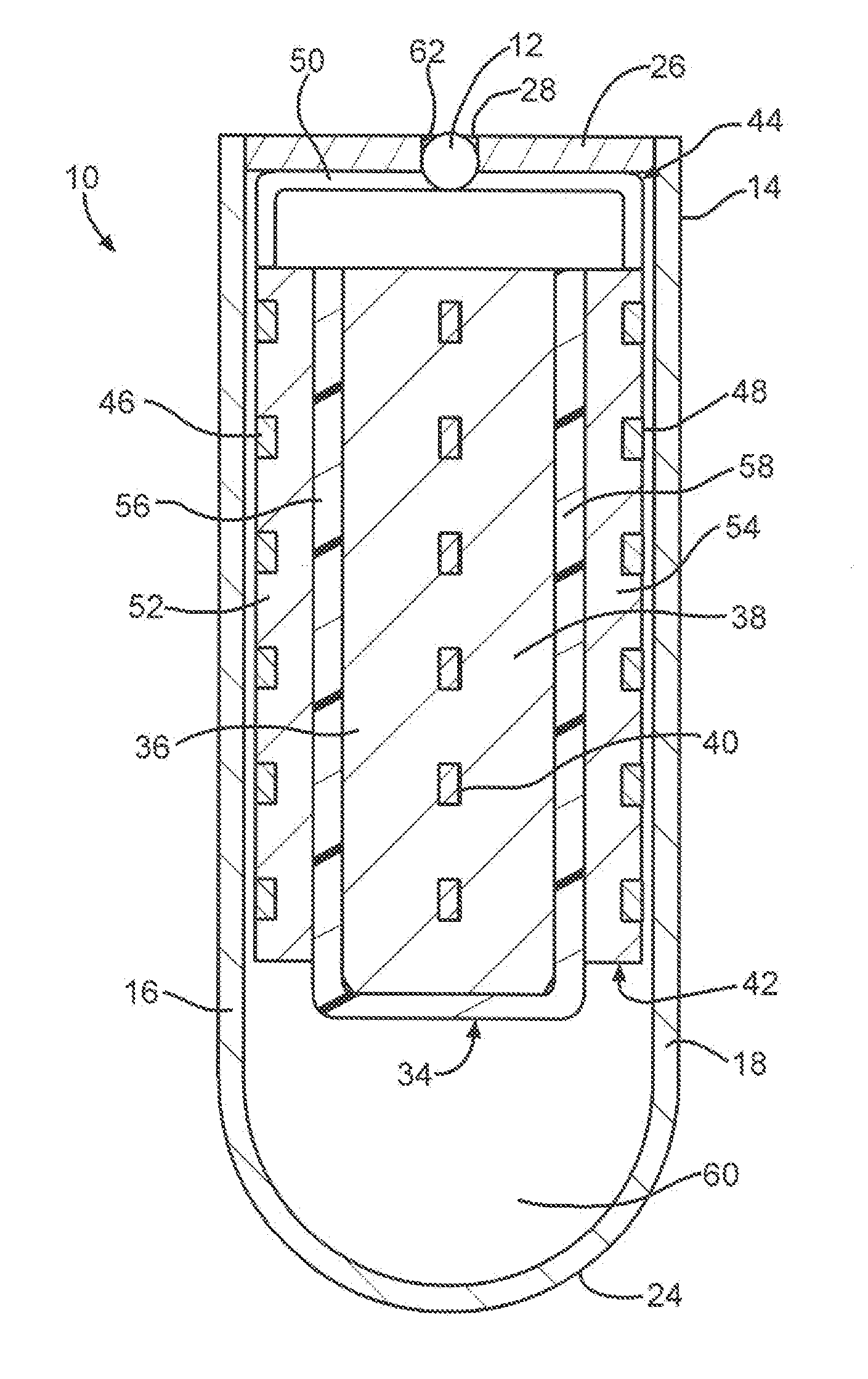
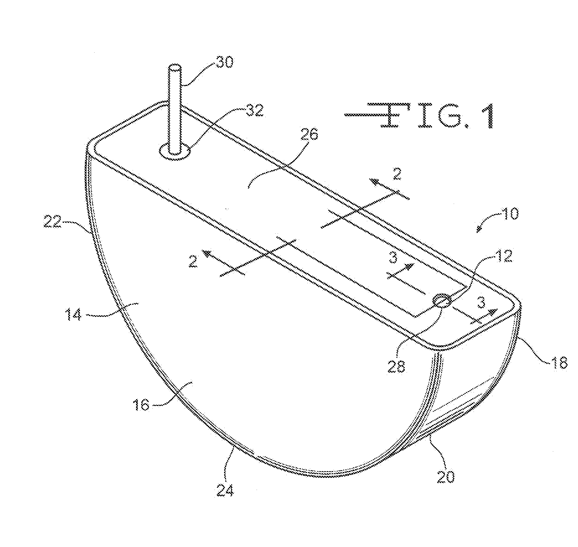
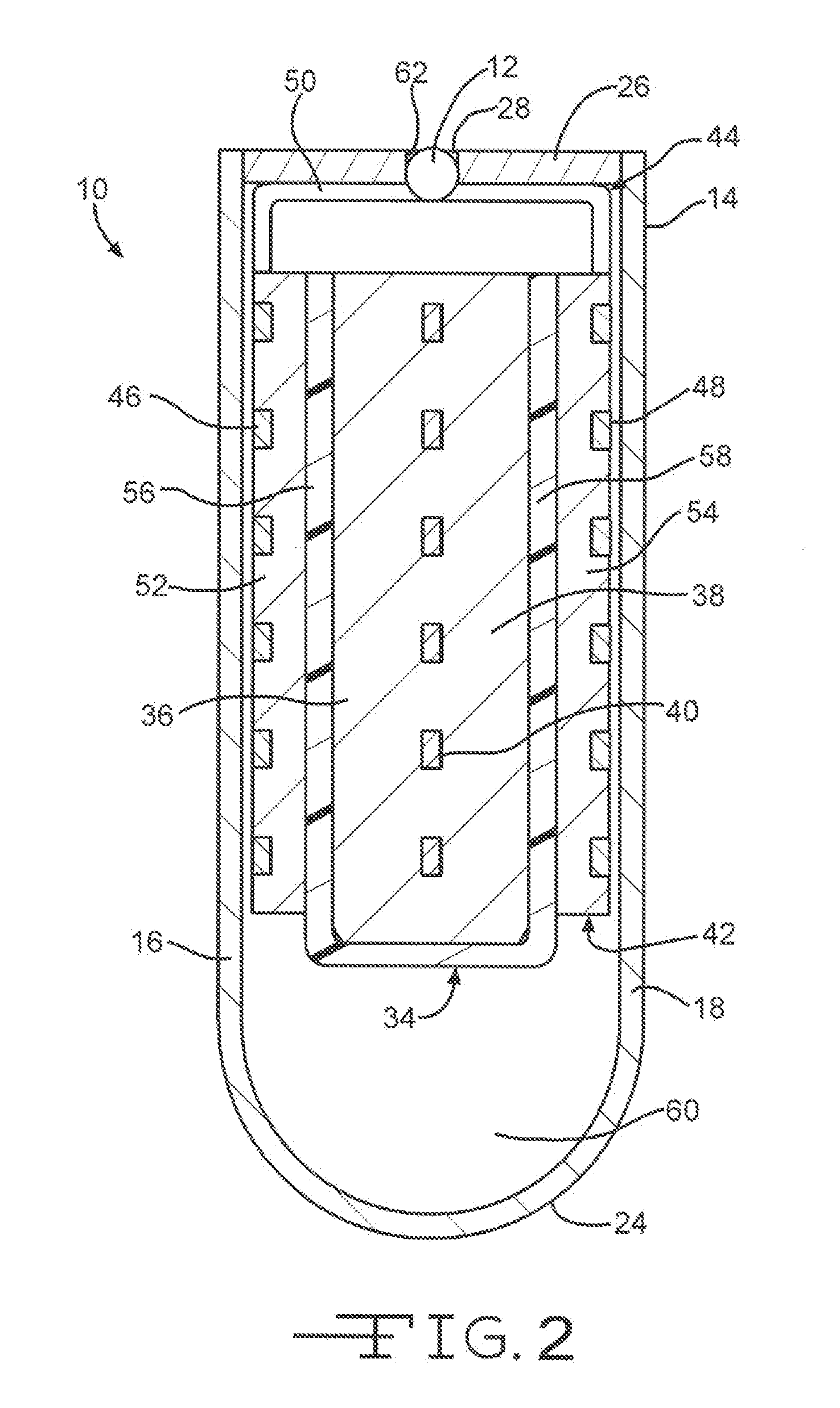
[0045] Referring now to the drawings, FIG. 1 shows a perspective view and FIG. 2 shows a cross-sectional view of an exemplary electrochemical cell 10 as a hermetic device provided with hermetic sealing means, for example, spherical shaped sealing member 12. While cell 10 is shown having a half-rounded shape, it will be readily apparent to those skilled in the art that in their broadest form such ...


PUM

PropertyMeasurementUnit
Percent by massaaaaaaaaaa
Weightaaaaaaaaaa
Saturation temperatureaaaaaaaaaa

Abstract

An apparatus for making a hermetic device containing a detectable gas and comprising a surface having a fill port comprising a vacuum pump in communication with the hermetic device through a vacuum conduit; a liquid reservoir for containing liquid to be delivered to the hermetic-device; a gas reservoir for containing a detectable gas to be delivered to the hermetic device; a transfer vessel for transferring a selected quantity of liquid and gas to the hermetic device; and a block for passing the selected quantity of liquid and gas through a fill port of the hermetic device, and disposing a seal into the fill port. A method for making a hermetic device containing a detectable gas, and an exemplary hermetic device comprising an electrochemical cell or a capacitor are also disclosed.

Description

CROSS-REFERENCE TO RELATED PATENT APPLICATIONS [0001] This application claims priority from U.S. Provisional Application Ser. No. 60 / 673,514, filed Apr. 22, 2005, the disclosure of which is incorporated herein by reference.BACKGROUND OF THE INVENTION [0002] 1. Field of the Invention [0003] The present invention generally related to quality control of hermetic devices and, more particularly, to leak detection of sealed enclosures to ensure their hermeticity after completion of manufacturing. Leak detection is enabled by providing a detectable gas within the container during the hermetic device manufacturing process. Confirming hermeticity is critical for any sealed enclosure, especially one housing an electrical power source for an implantable medical device. The power source can be either an electrochemical cell or a capacitor. [0004] In either case, the power source includes a negative electrode and a positive electrode physically segregated from each other by a separator and provi...

Claims


Application Information

Patent Timeline
IPC IPC(8): B65B1/04H01M50/179H01M50/184H01M50/186H01M50/636H01M50/673
CPCH01G9/08H01G13/04H01M2/06H01M2/08H01M10/4285H01M2/365H01M6/5083H01M10/4228H01M10/4235H01M2/361Y02E60/13Y02E60/10H01M50/636H01M50/673H01M50/179H01M50/184H01M50/186
Inventor PYSZCZEK, MICHAEL F.CANAPLE, NICOLAS
Owner WILSON GREATBATCH LTD
Learn More