Traverse-type window blind with multiple rods and blinds

Inactive Publication Date: 2006-11-23
NIEN LESLIE
11 Cites 20 Cited by

AI-Extracted Technical Summary

Problems solved by technology

However, there are some drawbacks to such conventional window blind structure.
When the blind bodies 20 are actuated in the opening or closing operation thereof, the support decorative bod...

Benefits of technology

[0004] It is, therefore, the primary purpose of the present invention to provide a traverse-type window blind with multiple rods and blinds, including brackets, support rods, sliding hooks, and blind bodies wherein each bracket has at least two or more support portions sequentially extending forwards at one side of an abutment face for the mounting of the support rods thereon respectively, and each sliding hook is equipped with a hooked upper portion larger than the support portion thereof so that the sliding hook can freely run on the support rod and move among traverse spaces defining the support portions of the brackets without being interfered in the operation to provide an easy traverse-type design thereby. Therefore, each blind body suspending between every two sliding hooks thereof can be precisely moved along the support rod relative to the position of sunlight to achieve accurate sunlight blocking effect thereby.
[0005] It is, therefore, the second purpose of the present invention to provide a traverse-type window blind w...

Abstract

A traverse-type window blind with multiple rods and blinds includes brackets, support rods, sliding hooks, and blind bodies wherein each bracket has an abutment face to be fixed to a sidewall of a window frame and at least two or more support portions sequentially arranged at the other side for the mounting of the support rods thereon respectively. Each sliding hook has a hooked upper portion larger than the support portion thereof to be guided through traverse spaces defining the support portions and hanged onto the support rod thereby so that each blind body suspending between every two sliding hooks can be synchronically moved along the support rod without being interfered in an easy traverse-type operation. Besides, each sliding hook has a protective member mounted to the hooked upper portion so as to avoid direct contact with the surface of the support rod and refrain from any damages caused thereby.

Application Domain

Door/window protective devicesCurtain suspension devices +5

Technology Topic

EngineeringWindow shutter +1

Image

  • Traverse-type window blind with multiple rods and blinds
  • Traverse-type window blind with multiple rods and blinds
  • Traverse-type window blind with multiple rods and blinds

Examples

  • Experimental program(1)

Example

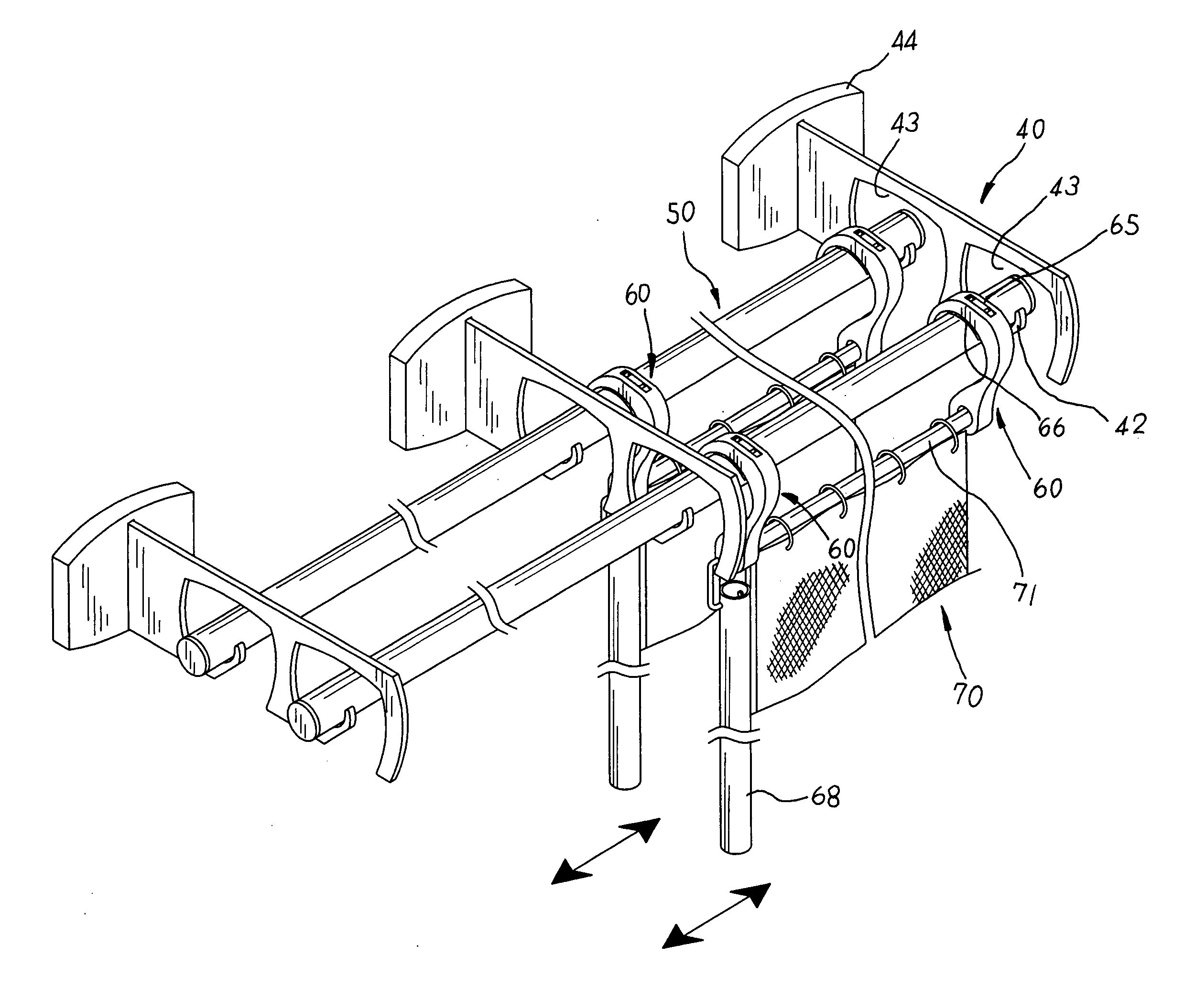
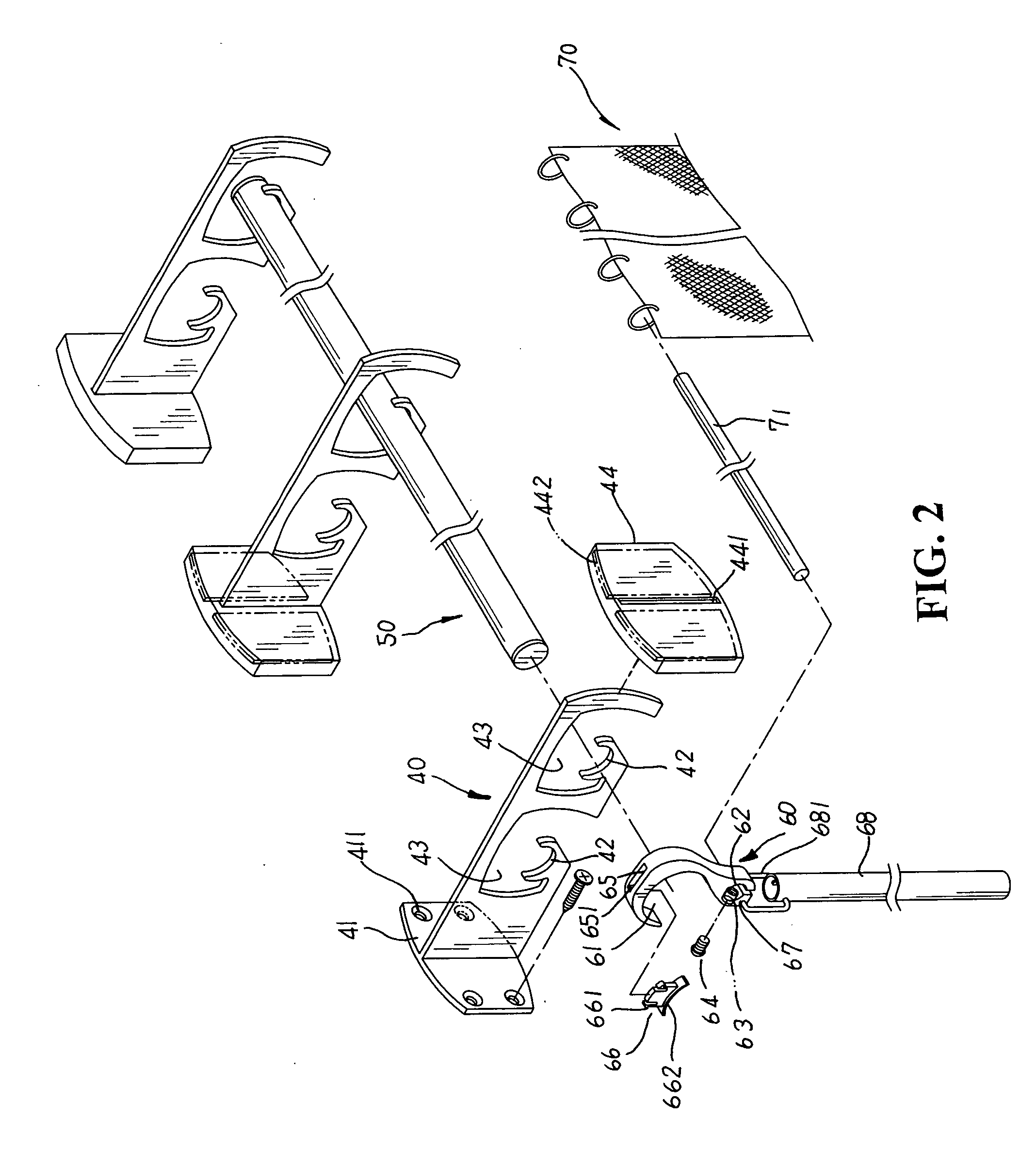
[0014] Please refer to FIGS. 2, 3. The present invention is related to a traverse-type window blind with multiple rods and blinds, including brackets 40, support rods 50, sliding hooks 60, and blind bodies 70. Each bracket 40 has an abutment face 41 with thru-holes 411 disposed at one side thereon to be fixedly locked to a sidewall of a window frame thereby, and at least two or more front and rear support portions 42 each having an arcuate support surface defining thereon are sequentially arranged in an equal space to extend forwards at one side of the abutment face 41 for the mounting of the support rods 50 thereon respectively. The outer periphery of each support portion 42 is defined by an inverted U-shaped traverse space 43, and a decorative cover 44 is provided to apply to the outer side of the abutment face 41 thereon, permitting an even and neat look of the bracket 40 thereby. The decorative cover 44 identically shaped like the abutment face 441 thereof has a passable slot 441 disposed in the middle thereon to thread through the support portions 42 thereby, and a pair of magnetic attachment articles 442 symmetrically fixed at both sides thereof to be magnetically attached to the abutment face 41 for location thereon. Each sliding hook 60 (referring to FIG. 4) is made up of a hooked upper portion 61 shaped in a hooked curvature larger than that of the support portion 42 to be led through the traverse space 43 thereof and hanged onto the support rod 50 thereby. The lower section of the sliding hook 60 is disposed a sleeve hole 62 for the location of each end of a hanging rod 71 with one blind body 70 mounted thereto, permitting each blind body 70 to precisely suspend and hang between every two sliding hooks 60 thereby. At one peripheral wall of the sleeve hole 62 thereof is perpendicularly disposed a screw hole 63 for the locking of a screw 64 there-through to abut tight against the circumferential surface of the hanging rod 71 thereon, and at the top side of the hooked upper portion 61 is equipped with a slot-like assembly section 65 with a stepwise stop flange 651 disposed therein to be reciprocally coupled with a plastic protective member 66 thereby. The protective member 66 has a set of insert hooks 661 protruding at the top thereof to precisely engage with the stop flange 651 of the assembly section 65 and form an even and flat surface therewith, and an arcuate sliding surface 662 is disposed defining the bottom side of the protective member 66 to accurately abut against the inner wall of the hooked upper portion 61 thereof and contact with the circumferential surface of the support rod 50 thereby. Beneath the screw hole 63 of the sliding hook 60 thereof is disposed a fixing hole 67 for the suspending location of a hanging ring 681 with a pull rod 68 attached thereto.
[0015] In application, the hooked upper portion 61 of the sliding hook 60 larger than the support portion 42 of the bracket 40 can freely pass through the traverse space 43 thereof (referring to FIG. 4), permitting the sliding hook 60 to slide along the support rod 50 and move among the traverse spaces 43 and the support portions 42 of the brackets 40 without being interfered in the operation thereof to provide an easy traverse-type design thereby. Therefore, the blind body 70 suspending on each hanging rod 50 can be freely moved and accurately shifted in position relative to that of sunlight to achieve better sunlight blocking effect thereby. Meanwhile, the pull rod 68 is simply drawn to synchronically actuate the movement of the sliding hooks 60, the hanging rod 71 and the blind body 70 in a linkage operation, preventing any direct and repeated contact with the blind body 70 so as to avoid partial untidy stains or marks left thereon in the operation thereof. Besides, the protective member 66 is applied to separate each sliding hook 60 from the support rod 50 thereof to prevent the sliding hook 60 running on the support rod 50 thereof from directly rubbing against the surface of the support rod 50 and causing scratching damages thereon, efficiently achieving the purpose of protection and the durability of the present invention in application thereof.
[0016] Please refer to FIG. 5 showing an exploded perspective view of another embodiment of the present invention. The present invention can also be made up of brackets 40′ each having an outermost support portion 42′ defined by an open-type traverse space 43′, and an innermost support portion 42′ defined by a narrower traverse space 43′. And, sliding hooks 60′ are provided each made into a thin-plate form with a size adapted to that of the traverse space 43′ and the support portions 42′ thereof. The sliding hook 60′ is equipped with a hooked upper portion 61′ larger than the support portion 42′ to be guided through the traverse space 43′ and hanged onto the support rod 50 thereby. At the top side of each sliding hook 60′ thereof is mounted a plastic and U-shaped protective member 66′, and a U-shaped assembly section 65′ is disposed at an appropriate position of the hooked upper portion 61′ therein for insert ribs 661′ symmetrically extending at the top edge of the protective member 66′ thereof to precisely engage and form an even and flat surface therewith. The bottom side of the protective member 66′ is defined by an arctuate sliding surface 662′ to abut against the inner wall of the hooked upper portion 61′ and contact with the circumferential surface of the support rod 50 thereby. The sliding hook 60′ also includes a set of first and second screw holes 62′, 63′ horizontally arranged in an equal space at the lower section thereon. And hanging rods 71′ are provided each having fixing ends 711′ disposed at both sides thereon to be securely locked to the first screw hole 62′ of a sliding hook 60′ respectively, permitting the blind body 70 attached to each hanging rod 71′ thereon to precisely suspend and hang between every two sliding hooks 60′ thereby. Therefore, the hooked upper portions 61′ of the sliding hooks 60′ can freely run on the support rod 50 without being interfered by the bracket 40′ as shown in FIG. 6. In addition, a linkage plate 64′ with a plurality of assembly holes 641 disposed thereon is reciprocally locked to the second screw hole 63′ thereof for location thereon, and one end of the linkage plate 64′ is bent into an appropriate angle and extend for a proper length to provide a push guiding portion 642′. Then, the sliding hooks 60′ of paired-up support rods 50 are symmetrically hanged in opposite directions, permitting the push guiding portions 642′ of the corresponding linkage plates 64′ to precisely overlap in pairs. Therefore, the blind body 70 mounted to one of the paired-up support rods 50 thereof is drawn to actuate the synchronic movement of the other blind body 70 mounted to the other paired-up support rod 50 as shown in FIG. 7.

PUM

no PUM

Description & Claims & Application Information

We can also present the details of the Description, Claims and Application information to help users get a comprehensive understanding of the technical details of the patent, such as background art, summary of invention, brief description of drawings, description of embodiments, and other original content. On the other hand, users can also determine the specific scope of protection of the technology through the list of claims; as well as understand the changes in the life cycle of the technology with the presentation of the patent timeline. Login to view more.

Similar technology patents

Flexible wiring and tubing carrier for slide-out rooms

ActiveUS6930244B1simple in construction and installationpresent invention
Owner:LIPPERT COMPONENTS

Adhesive composition and method for temporarily fixing member by using the same

ActiveUS20100000670A1high adhesive strengthpresent invention
Owner:DENKA CO LTD

Pyrido[3,2-d]Pyridazine-2(1H)-One Compounds as p38 Modulators and Methods of Use Thereof

InactiveUS20110281864A1modulate activityblock effect
Owner:AMGEN INC

Binding agents

ActiveUS20070110747A1block effect
Owner:UCB SA +1

Pyridazino-pyridinone Compounds and Methods of Use

InactiveUS20110275629A1modulate activityblock effect
Owner:AMGEN INC

Classification and recommendation of technical efficacy words

  • present invention
  • block effect

Flexible wiring and tubing carrier for slide-out rooms

ActiveUS6930244B1simple in construction and installationpresent invention
Owner:LIPPERT COMPONENTS

Adhesive composition and method for temporarily fixing member by using the same

ActiveUS20100000670A1high adhesive strengthpresent invention
Owner:DENKA CO LTD

Binding agents

ActiveUS20070110747A1block effect
Owner:UCB SA +1

Pyrido[3,2-d]Pyridazine-2(1H)-One Compounds as p38 Modulators and Methods of Use Thereof

InactiveUS20110281864A1modulate activityblock effect
Owner:AMGEN INC

Pyridazino-pyridinone Compounds and Methods of Use

InactiveUS20110275629A1modulate activityblock effect
Owner:AMGEN INC
Why Eureka
Try Eureka