Sunshade actuation device

a technology of sunshade and actuation device, which is applied in the direction of roofs, windows, transportation and packaging, etc., can solve the problems of not being able to provide another component in the area between the guide rails, requiring a larger mounting space, and wasting or dead space. , to achieve the effect of small and lightweight, simple structure, and discharge or reduce the force against the foreign member

Active Publication Date: 2006-11-23
TOYOTA BOSHOKU KK +1
View PDF22 Cites 29 Cited by
  • Summary
  • Abstract
  • Description
  • Claims
  • Application Information

AI Technical Summary

Benefits of technology

[0015] The first aspect of the sunshade actuation device includes a structure in which the guide body extends in a curved shape, and the mounting part of an arm member to the screen pivots with respect to the engaging part interfacing with the guide body due to the arm member moving along the guide body. Consequently, it is possible to cause the arm member to rotate through the use of a single guide body. In addition, it is not only possible to broadly draw the screen out in comparison with the length of the guide body (i.e., the drawing length of the screen is greater than the sliding length of the guide body), but it is also possible to achieve a sunshade actuation device that is relatively small and lightweight.
[0016] The sunshade actuation device of the second aspect comprises an escape device for allowing the arm member to rotate in a direction away from the winding device when the arm member abuts against a foreign member so as to receive a load during movement toward the winding device. Therefore, it is possible to discharge or reduce the force against the foreign member even if the arm member becomes entangled during the winding motion.
[0017] In the sunshade actuation device of the third aspect, the arm member includes a moving part mounted to the screen. The arm part is engaged with the guide body while connected to the moving part. The moving part can move relative to the arm part so as to absorb differences between a drawing locus or center of the screen, and a moving locus or center of the mounting part of the arm member relative to the screen. As a result, it is possible to draw the screen out without generating wrinkles in the screen through the use of a relatively simple structure.
[0018] The sunshade actuation device of the fourth aspect includes a winding device that has a mounting shaft fixed near the window. The roller member is rotatably mounted to the mounting shaft. The screen is wound around the roller member. The roller member can move relative to the mounting shaft in an axial direction in order to absorb differences between a drawing locus of the screen and a moving locus of the mounting part of the arm member relative to the screen. Therefore, it is possible to draw the screen out without causing winkles in the screen through the use of a relatively simple structure.
[0019] The sunshade actuation device according to the fifth aspect includes a winding device that has a tapered roller member, which can rotate and around which the screen is wound. The outer diameters of the ends of the tapered roller member are configured correspondingly different so that a drawing center of the screen may follow a center locus of the mounting part of the arm member relative to the screen. Consequently, it is possible to draw the screen out and by using a relatively simple structure, simultaneously inhibit the generation of wrinkles in the screen.
[0020] The sunshade actuation device of the sixth aspect includes a winding device that includes the roller member, which can rotate and around which the screen is wound. The roller member can incline (pivot) in a drawing direction of the screen so that the drawing direction of the screen may correlate to a moving direction of the mounting part of the arm member relative to the screen. Therefore, it is possible to draw the screen out without generating wrinkles in the screen through the use of a relatively simple structure.

Problems solved by technology

In the conventional technology sunshade actuation device, since the arm member slides while engaging with the pair of guide rails, which have a predetermined angle there between, it is not realistically possible to provide another component in the area between the guide rails.
As a result, this area becomes a wasted or dead space.
Consequently, a larger mounting space is required.

Method used


Image

  • Sunshade actuation device
  • Sunshade actuation device
  • Sunshade actuation device

Examples


embodiment 1

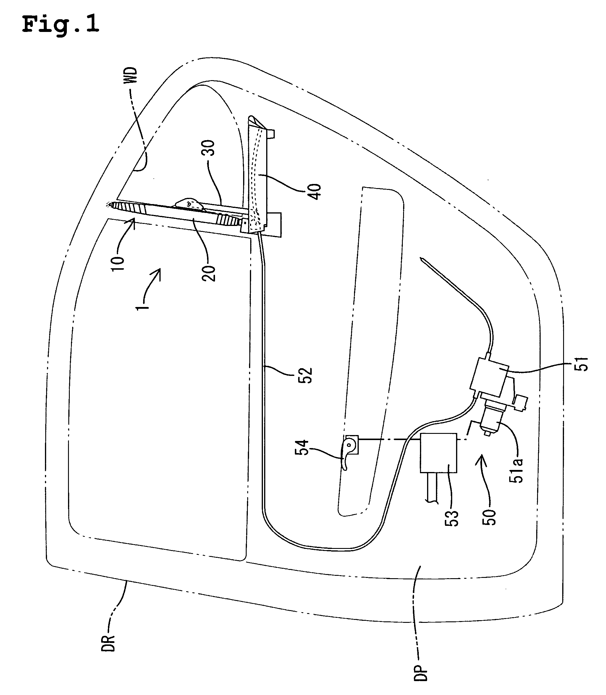
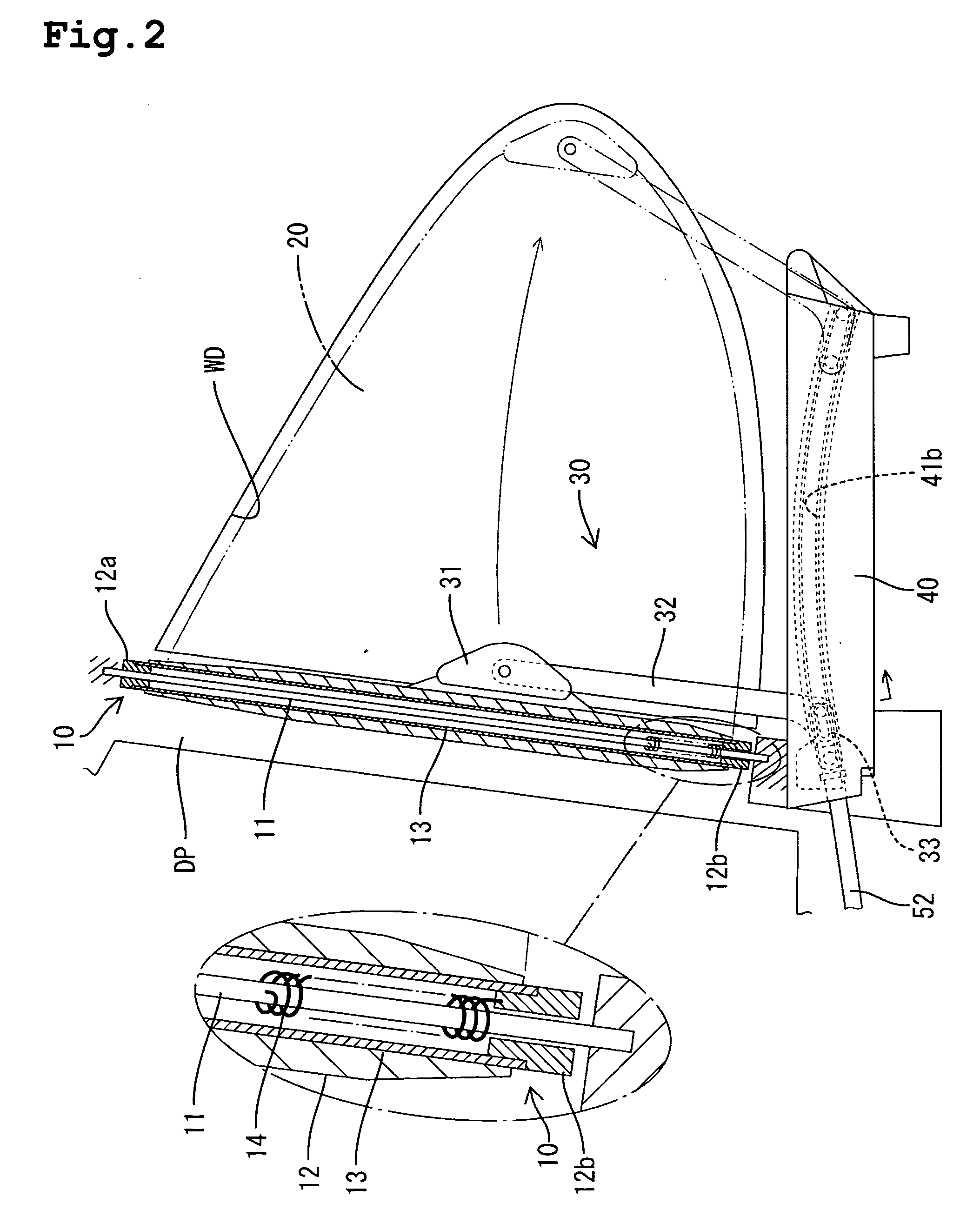
[0031] A first embodiment of the present invention will be explained with reference to FIGS. 1 to 6. The left side of the FIG. 1 is referenced as the front in the explanations, the right side is the rear. As shown in FIG. 1, a sunshade actuation device 1 is mounted in a door panel DP, which constitutes a rear door DR of a vehicle. The sunshade actuation device 1 comprises a winder 10, a shade member 20, a swing arm device 30, a guide rail assembly 40, and an actuator device 50.

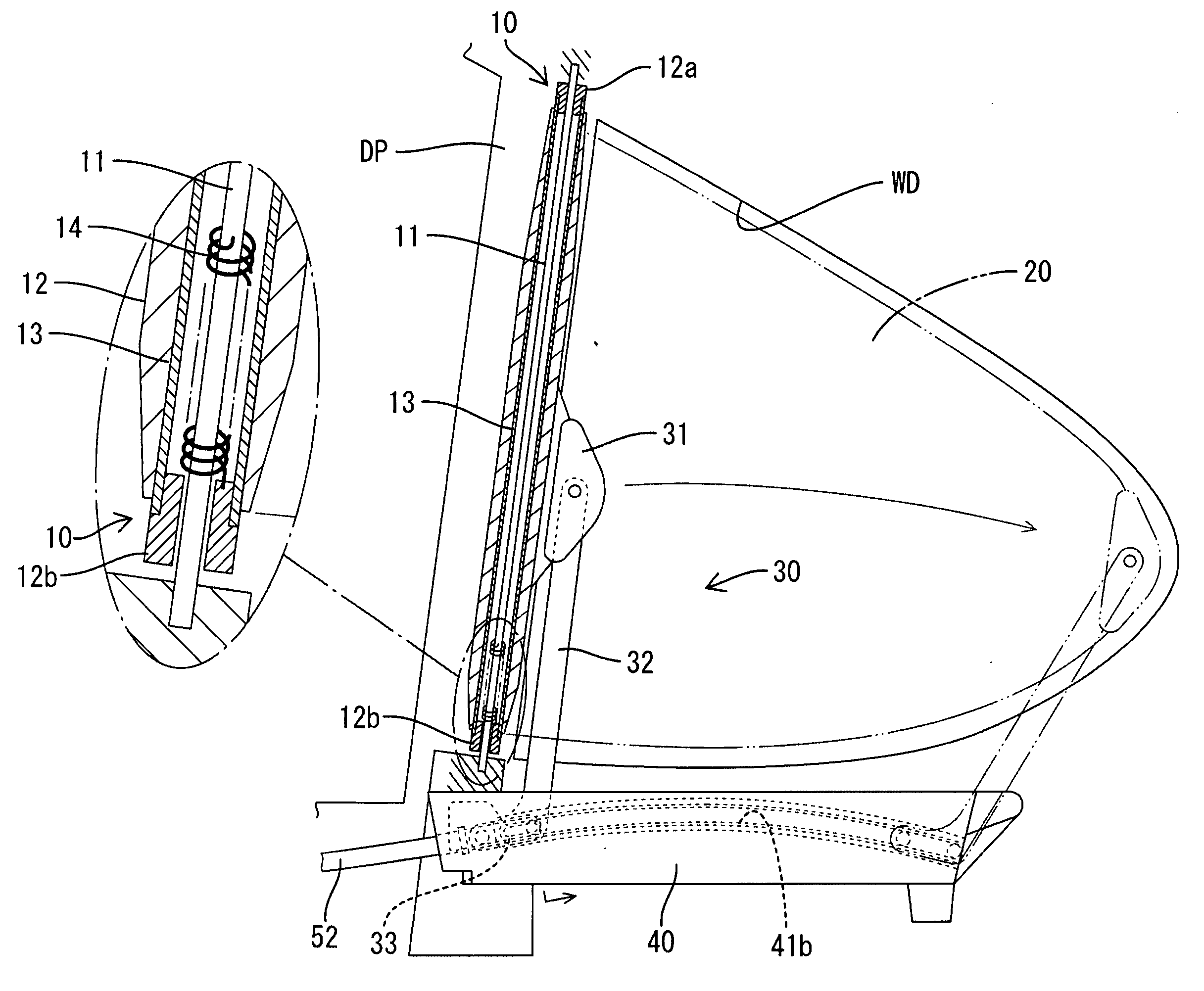
[0032] The winder 10 (see FIG. 2) (corresponding to an example of a winding device) is arranged proximate to (i.e., in front of) a rear quarter window WD (corresponding to an example of a window) of the rear door DR, and is fixed to the door panel DP. A pair of roller caps 12a and 12b is rotatably mounted to each end of a mounting shaft 11. The mounting shaft 11 is unrotatably fixed to the door panel DP so as to be located proximate to the quarter window WD. In addition, a roller sleeve 13 is integrated with ...

embodiment 2

[0044] A second embodiment of the present invention will be explained next with reference to FIG. 7. In a connecting piece 34 (corresponding to an example of the moving part of the present invention) of the swing arm device 30A of this embodiment, an elongated hole 34a extends in an approximately vertical direction. Further, by inserting a rotation pin 32c within this elongated hole 34a, the drawing arm 32 is rotatably connected to the connecting piece 34. Thus, the connecting piece 34 can move relative to the drawing arm 32 in the vertical direction. The difference between the drawing locus of the rear portion of the shade member 20, when the shade member 20 is drawn out from the winder 10 or is wound by the winder 10, and the moving locus of the connecting piece 34, is absorbed by the vertical movement. Therefore, it becomes possible to draw the shade member 20 out, without the generation of wrinkles, through the use of a relatively simple structure.

embodiment 3

[0045]FIG. 8 shows a third embodiment of the present invention. In this embodiment, the roller caps 12a and 12b and the roller sleeve 13 of a winder 10A are made movable in an axial direction relative to the mounting shaft 11. The roller caps 12a and 12b and the roller sleeve 13 are hung from the mounting shaft 11 by the volute spring 14, intermediately installed between the mounting shaft 11 and the roller cap 12b. Therefore, the roller sleeve 13 can move relative to the mounting shaft 11 in an axial direction (i.e., a vertical direction as viewed in FIG. 8) due to an adequate load. The difference between the drawing locus of the rear portion of the shade member 20, when the shade member 20 is drawn out from the winder 10A or is wound by the winder 10A, and the moving locus of the connecting piece 31, can be absorbed by the vertical movement of the roller sleeve 13. Consequently, it becomes possible to draw the shade member 20 out, without the generation of wrinkles, through the us...


PUM


Abstract

A winder is provided near a quarter window of a rear door. A shade member is drawably mounted about the winder. A connecting piece is connected to a drawing arm and mounted to the rear portion of the shade member. A shoe is mounted to a bottom end of the drawing arm. The shoe engages with a regulatory groove extending in a drawing direction of the shade member. A driving cable is connected to the shoe. The shade member can be drawn out across the window by the drawing arm via the sending out of the driving cable by an operating mechanism. Since the regulatory groove extends substantially in a circle, when the shoe moves through engagement with the regulatory groove, the connecting piece connected to the drawing arm pivots relative to the shoe.

Description

BACKGROUND OF THE INVENTION [0001] 1. Field of the Invention [0002] The present invention relates to a sunshade actuation device that opens and closes a screen for covering a window. [0003] 2. Description of the Related Art [0004] There exists conventional technology concerning a sunshade actuation device for the opening and closing of a sunshade for covering a vehicle window (e.g., refer to Germany Patent No. 19826537). This sunshade includes a pair of guide rails that have a non-parallel mutual relationship in a lower part of a vehicle window, and an arm member, which is equipped with respective engaging parts engaged with the pair of guide rails and extends upwards to be connected to a screen. The screen can be drawn out to cover the window. Since the arm member slides in a fore-and-aft direction via a cable in the state of engaging with the guide rails, the screen connected to the cable is drawn out from a winding device. Therefore, it is possible to cover and uncover the window...

Claims


Application Information

Patent Timeline
Patent Type & Authority Applications(United States)
IPC IPC(8): B60J1/20
CPCB60J1/2027B60J1/2075B60J1/2072
Inventor TAKEUCHI, KOUICHITAMAKI, AKIHIROYOO, YEONG-HAK
Owner TOYOTA BOSHOKU KK
Why Eureka
Try Eureka