Manufacturing method of carrier

a manufacturing method and carrier technology, applied in the direction of surface layering apparatus, manufacturing tools, applications, etc., can solve the problems of increasing the percentage of faulty products, complicated injection molding process, and changing the dimensions of holes, so as to minimize errors or corrections

Inactive Publication Date: 2006-11-23
HYUNDAI MOBIS CO LTD
View PDF5 Cites 0 Cited by
  • Summary
  • Abstract
  • Description
  • Claims
  • Application Information

AI Technical Summary

Benefits of technology

[0019] The manufacturing method of hybrid-carrier has its holes made in and the nuts fixed in the carrier which has undergone a complete deformation, thereby minimizing the errors or corrections when attaching other parts to the hybrid-carrier even if the hybrid-carrier undergoes deformation during the process of solidification after being injection-molded.

Problems solved by technology

However, there are problems with the manufacturing process described above as follow.
Firstly, since the holes for assembling the headlamp or bumper with the hybrid-carrier in the injection molding process are undercut parts in the pullout direction of the injection mold, there is a problem in that the injection molding process becomes complicated with the need of applying a slide core to it.
Secondly, as the deformation of the molded hybrid-carrier occurs by undergoing a cooling process after the holes for assembling the parts are drilled through, there is a problem in that a gap or divergence in heights with the parts is formed and the dimensions of the holes are changed.
Thirdly, as the deformation of the molded hybrid-carrier occurs before the carrier is completely solidified during the cooling process after injection-molding process, there is a problem in that the percentage of faulty products is increased with the occurrence of diffusion of air-bubbles in the holes during nutserting process.
Fourthly, due to the deformation of the hybrid-carrier shown above, there is a problem in that the time taken to maximize the quality of products is lengthened by the errors in the shape of the hybrid-carrier and the incorrect elevation of injecting.
Lastly, since an additional correction device with sensor is required in order to correct the gap or divergence in heights due to deformation of the hybrid-carrier, there is a problem in that such a correction device is expensive which makes the cost of manufacturing higher.

Method used


Image

  • Manufacturing method of carrier
  • Manufacturing method of carrier

Examples


Embodiment Construction

[0024] Preferred embodiments will now be described in detail with reference to the accompanying drawings.

[0025] Further, in the following description, the present embodiments are disclosed for example only, and not to limit the scope of the present invention. The same components as those of the conventional manufacturing method of hybrid-carrier will be denoted by the same reference numerals.

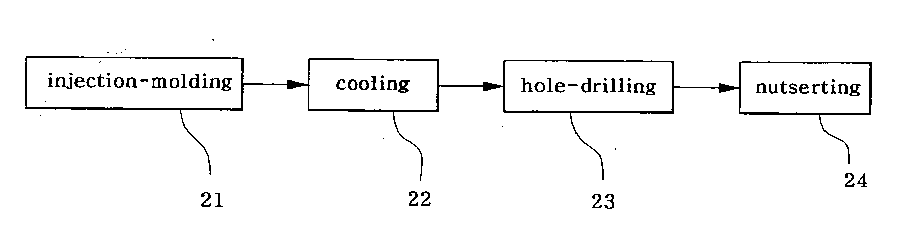
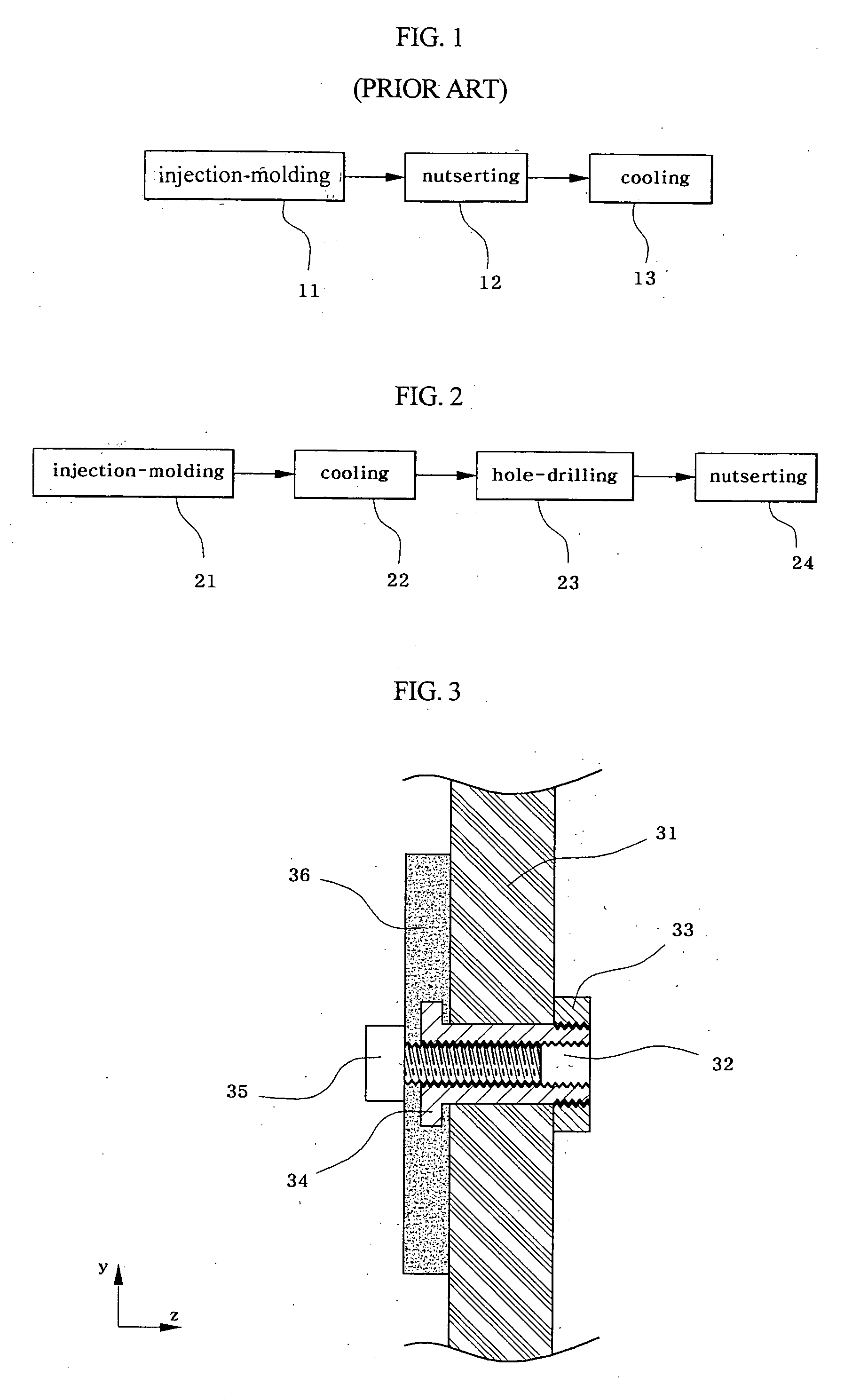
[0026]FIG. 2 is a block view briefly illustrating a manufacturing process of hybrid-carrier according to the present invention,

[0027] As shown in the drawings, the manufacturing method of hybrid-carrier according to the present invention comprises of steps, wherein the outer shape of the hybrid-carrier is injection-molded first 21, then, the injection-molded hybrid-carrier is solidified by cooling it down 22, holes for assembling the parts are made in the solidified hybrid-carrier above 23, and nuts are fixed in the hybrid-carrier in which the holes have been made.

[0028] That is, to describe...


PUM

PropertyMeasurementUnit
dimensionsaaaaaaaaaa
shapeaaaaaaaaaa
timeaaaaaaaaaa

Abstract

A manufacturing method of a hybrid-carrier includes injection-molding the hybrid-carrier, solidifying the injection-molded hybrid-carrier by cooling it down, making holes in the solidified hybrid-carrier to attach other parts to the hybrid-carrier, and mounting nuts on the hybrid-carrier in which the holes are made. The hybrid-carrier is manufactured by the above method in that holes are made in and nuts are mounted on the hybrid-carrier whose deformation is already complete even if the hybrid-carrier undergoes deformation during the process of solidification after being injection molded, thereby minimizing the errors and corrections when mounting other parts to the hybrid-carrier.

Description

RELATED APPLICATIONS [0001] The present disclosure relates to subject matter contained in Korean Application No. 10-2005-37688, filed on May 4, 2005, which is herein expressly incorporated by reference in its entirety. BACKGROUND OF THE INVENTION [0002] 1. Field of the Invention [0003] The present invention relates to a manufacturing method of a hybrid-carrier, made of plastic and steel, which undergoes deformation after injection-molding, wherein the holes for assembling the parts that are to be mounted on the hybrid-carrier are drilled in the carrier, thereby correcting the dimensions of the holes precisely, and reducing the cost of manufacturing. [0004] 2. Description of the Related Art [0005] In general, a vehicle frame, defining the outer appearance of a vehicle, comprises a passenger cabin, an engine compartment, a trunk compartment, fenders, and the like. The vehicle frame is divided into a front vehicle frame, a central vehicle frame, and a rear vehicle frame, in a lengthwis...

Claims


Application Information

Patent Timeline
Patent Type & Authority Applications(United States)
IPC IPC(8): B27N3/08B29C53/00B29C51/00B28B19/00B29D99/00
CPCB29L2031/3005B29C45/0053B23P15/00
Inventor YOON, DUK-GEUN
Owner HYUNDAI MOBIS CO LTD
Why Eureka
Try Eureka