
Method and device for patient monitoring using dynamic multi-function device

a dynamic multi-function device and patient monitoring technology, applied in the field of simple wireless electrocardiogram monitoring, can solve the problems of large patient wired footprint, high risk of ami in coronary atherosclerosis, and common life-threatening complication of ami, so as to simplify synchronization and facilitate communication. , the effect of simple and low cost solution

Inactive Publication Date: 2016-11-22
CARDIAC TECH INT
View PDF5 Cites 0 Cited by
  • Summary
  • Abstract
  • Description
  • Claims
  • Application Information

AI Technical Summary

Benefits of technology

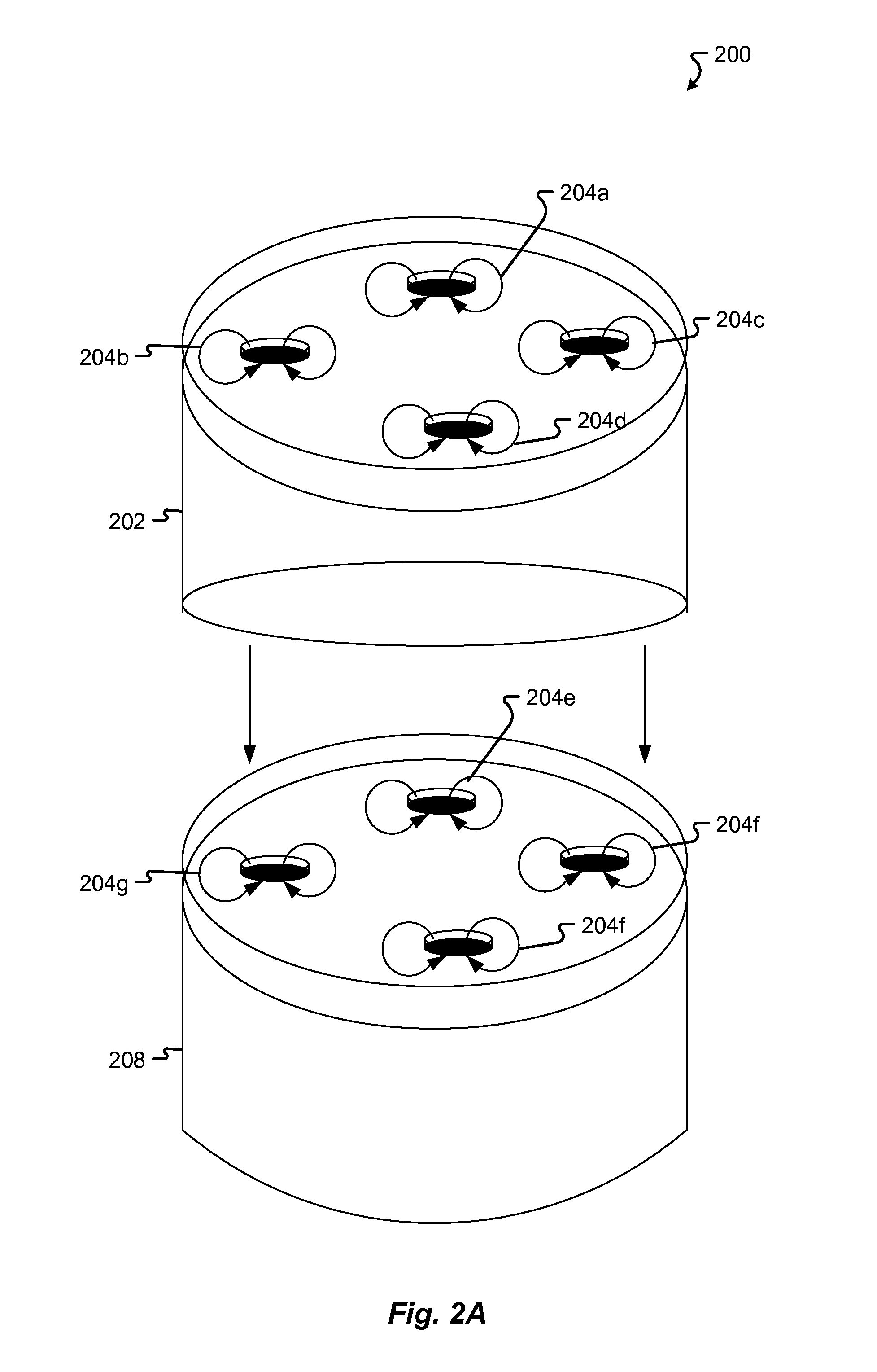
The invention is a wireless system for measuring the electrical activity of the heart using a leadless electrode assembly. This assembly includes a disposable electrode layer with multiple contact points for attachment to the patient's body. The system also includes a programmable device for real-time analysis of ECG information and can detect and treat abnormal heart rhythms. The invention minimizes signal interference and user error while reliably docking the monitoring device to the interface.

Problems solved by technology

AMI is a common and life-threatening complication of coronary artery disease.
Those with coronary atherosclerosis are at higher risk for AMI if the plaque becomes further obstructed by thrombus.
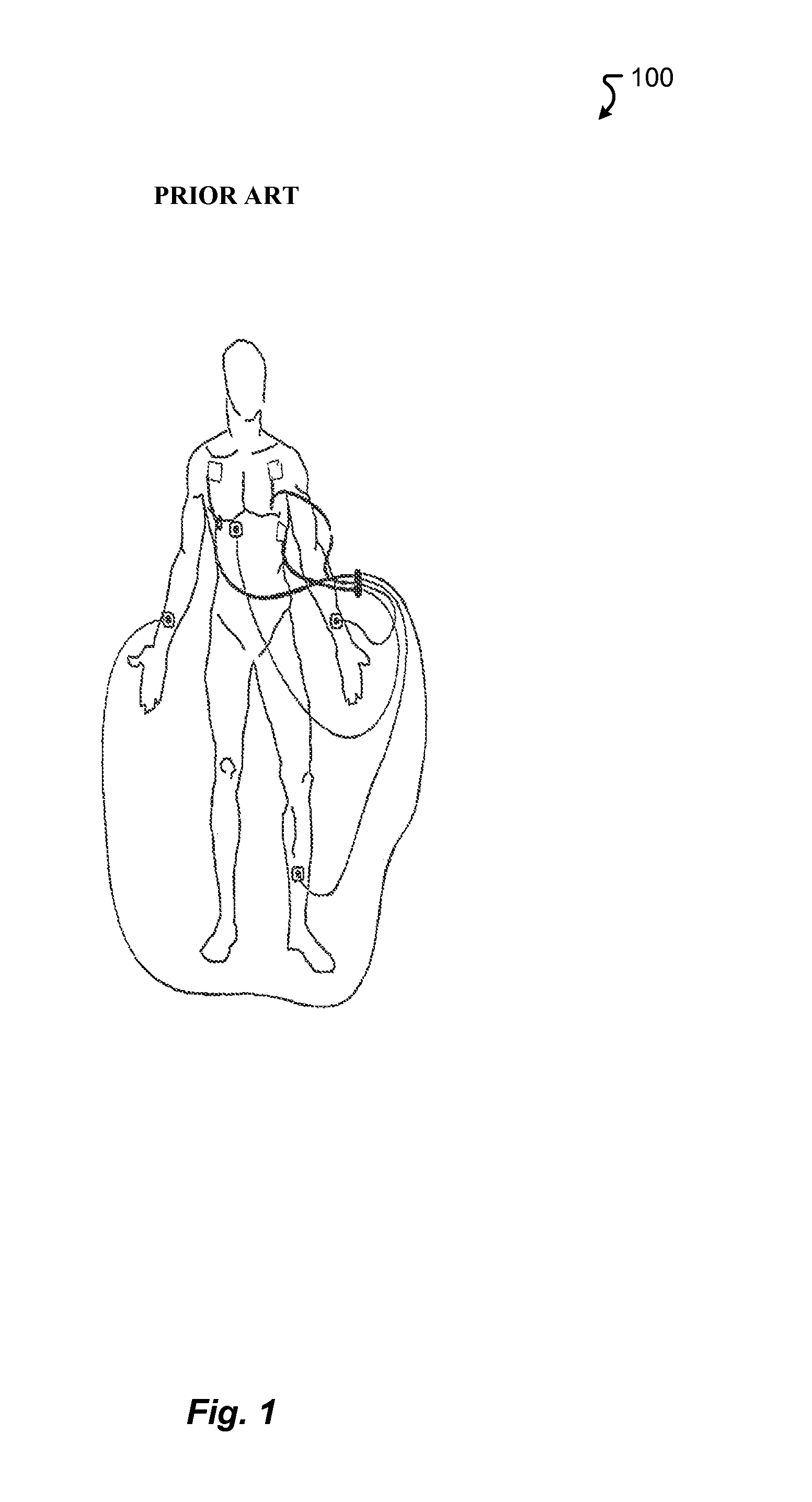
The required separation, leads to large wired footprints on the patient.
However, the variance in body impedance between different people is an evident source of error.
Further, the use of a wired monitoring system makes taking a patient's ECG very uncomfortable.
Even further, wired devices make patient monitoring very cumbersome for the practitioners and increases the probability of infection due to the exposure of bodily fluid by the wires.
However, this solution is not a complete wireless solution and the use of wired electrodes still makes it very cumbersome to work with.
However, this solution is not the most efficient.

Method used


Image

  • Method and device for patient monitoring using dynamic multi-function device
  • Method and device for patient monitoring using dynamic multi-function device
  • Method and device for patient monitoring using dynamic multi-function device

Examples


Embodiment Construction

[0145]In the following detailed description, numerous specific details are set forth in order to provide a thorough understanding of the disclosed techniques. However, it will be understood by those skilled in the art that the present embodiments may be practiced without these specific details. In other instances, well-known methods, procedures, components and circuits have not been described in detail so as not to obscure the present disclosure.

[0146]Although embodiments are not limited in this regard, discussions utilizing terms such as, for example, “processing,”“computing,”“calculating,”“determining,”“establishing”, “analyzing”, “checking”, or the like, may refer to operation(s) and / or process(es) of a computer, a computing platform, a computing system, a communication system or subsystem, or other electronic computing device, that manipulate and / or transform data represented as physical (e.g., electronic) quantities within the computer's registers and / or memories into other dat...


PUM


Abstract

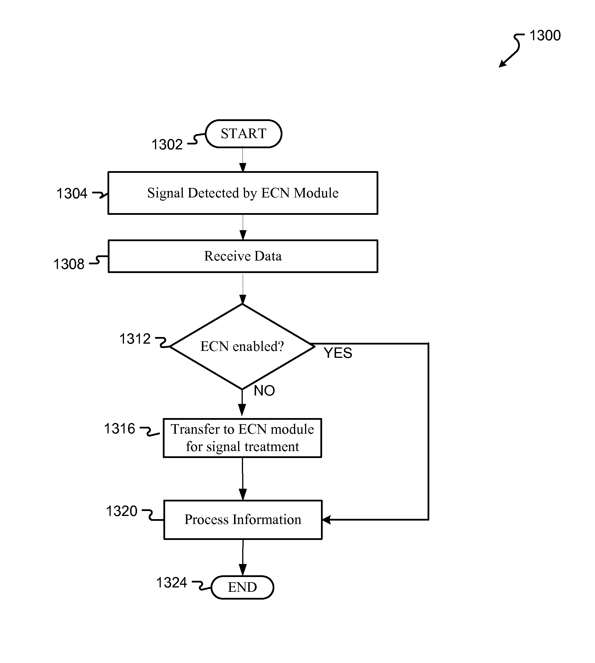
The present invention is directed to an improved method, system and product to provide wireless ECG patient monitoring. Although embodiments make specific reference to monitoring electrocardiogram signal with an adherent patch, the system methods, and device herein may be applicable to any application in which physiological monitoring is used. The present invention also presents a reliable means for docking the interface while minimizing signal interference and user error. In addition, a novel means for transmitting and receiving a patient's ECG measurements is introduced which includes the use of an epidermal communication network (ECN) and an ECG enabled module for ECN communications and interface. Although embodiments make specific reference to the use of the ECN for ECG measurements, the system methods, and protocol herein may be applicable to any wearable device and / or other smart device which is ECN enabled.

Description

FIELD OF THE INVENTION[0001]The present invention is directed to a method, system and device for simple wireless electrocardiogram monitoring. In particular, the invention is directed to the use of a wireless ECG with reliable functionality, data-log information access, intrinsically safe charging, and capacity to communicate via an epidermal communication network. Communication over the epidermal communication network can occur in conjunction with an epidermal communication network enabled module.BACKGROUND[0002]Heart disease is the leading cause of death in the United States. A heart attack, also known as an acute myocardial infarction (AMI), typically results from a blood clot or “thrombus” that obstructs blood flow in one or more coronary arteries. AMI is a common and life-threatening complication of coronary artery disease. Coronary ischemia is caused by an insufficiency of oxygen to the heart muscle. Ischemia is typically provoked by physical activity or other causes of increa...

Claims


Application Information

Patent Timeline
Patent Type & Authority Patents(United States)
IPC IPC(8): A61B5/00A61B5/0402A61B5/0408A61B5/0432
CPCA61B5/0402A61B5/6833A61B5/0028A61B5/0006A61B5/0432A61B5/04085A61B5/04087A61B5/6804A61B2560/0204A61B5/259A61B5/282A61B5/318A61B5/333G06F3/04855
Inventor BUCK, RYANHIJAZI, FREDERICK M.
Owner CARDIAC TECH INT
Learn More