
Compact, mechanically scanned cassegrain antenna system and method

Active Publication Date: 2006-11-23
THE BOEING CO
View PDF39 Cites 8 Cited by
  • Summary
  • Abstract
  • Description
  • Claims
  • Application Information

AI Technical Summary

Benefits of technology

[0007] The present invention is directed to a mechanically scanned antenna apparatus that requires a smaller swept volume than previously developed mechanically scanned antenna apertures. The present invention utilizes size, weight and power optimization techniques involving small, light weight components, and by reducing rotational radii, and torques through the use of lightweight, small components and composite construction.
[0010] In other preferred embodiments the main reflector and the support assembly are both of a composite construction to provide excellent structural strength yet light weight, as compared to other commonly used materials such as aluminum and / or steel. In one preferred form a subreflector is supported from a front surface of the main reflector and is also of a composite construction. The extensive use of lightweight composite materials and lightweight stepper motors, instead of common, heavier servo motor systems, eliminate the need for the use of weight counterbalances commonly used in antenna systems where the reflector, sub reflector and structure are fabricated of solid metal.
[0011] The various preferred embodiments provide a mechanically scanned antenna aperture that requires a smaller swept volume than previously developed mechanically scanned reflector antenna systems. In addition, the preferred embodiments are even lighter in weight than such traditional, mechanically scanned reflector antenna systems.

Problems solved by technology

The heavier the apparatus, the greater are the forces applied to the external surface of the aircraft, and the costlier is the structural reinforcement required for installation.
The added weight of the heavier apparatus, structural reinforcement and rotating components contribute to losses in fuel economy and reduction in the prime power of the mobile platforms.
RF losses degrade both EIRP and G / T in communications between mobile platforms near the earth and Ku- and Ka-band satellites in distant geostationary orbits.
The smaller and lighter the aperture structure is, the more likely that less powerful motors can be implemented.

Method used


Image

  • Compact, mechanically scanned cassegrain antenna system and method
  • Compact, mechanically scanned cassegrain antenna system and method
  • Compact, mechanically scanned cassegrain antenna system and method

Examples


Embodiment Construction

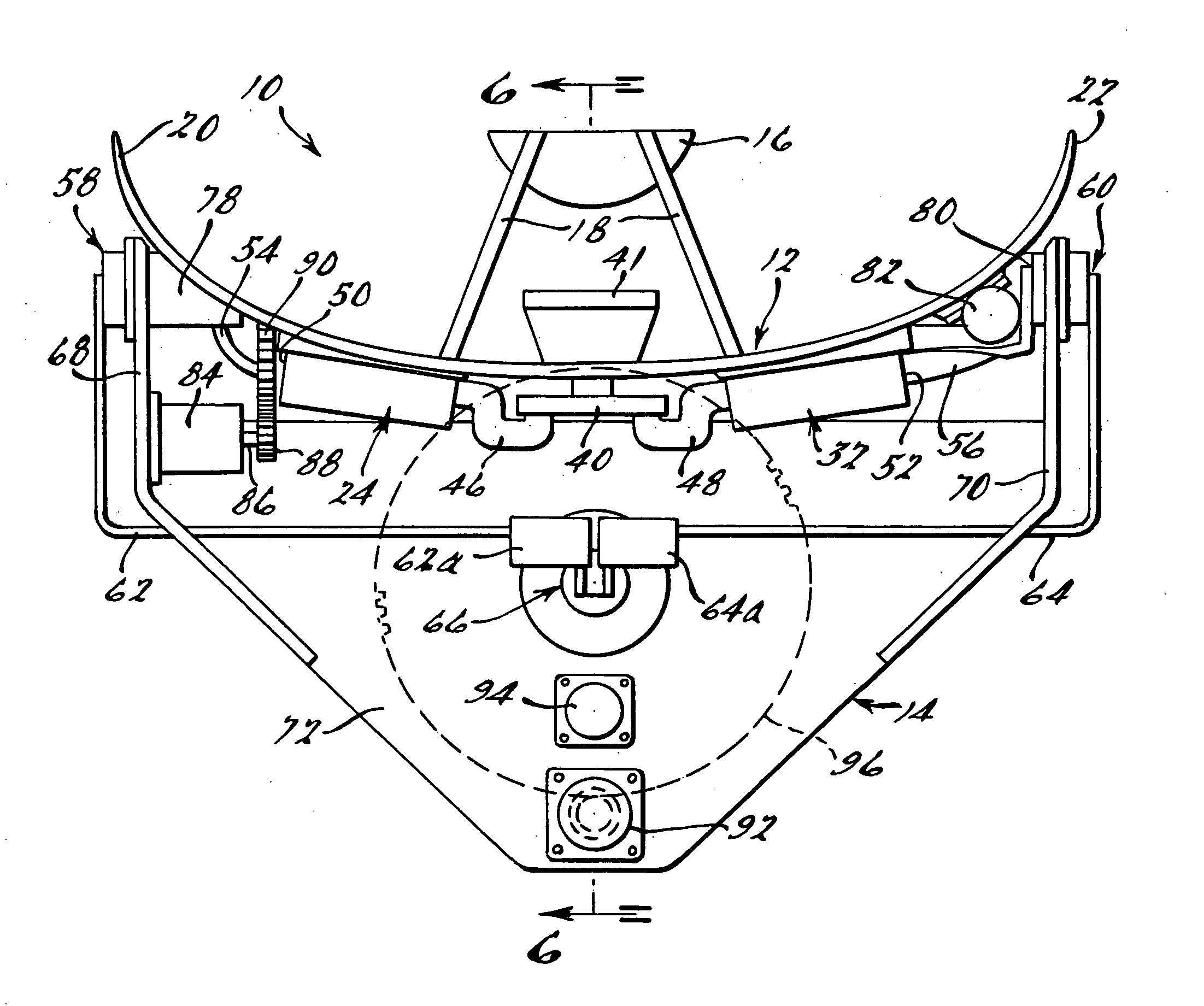
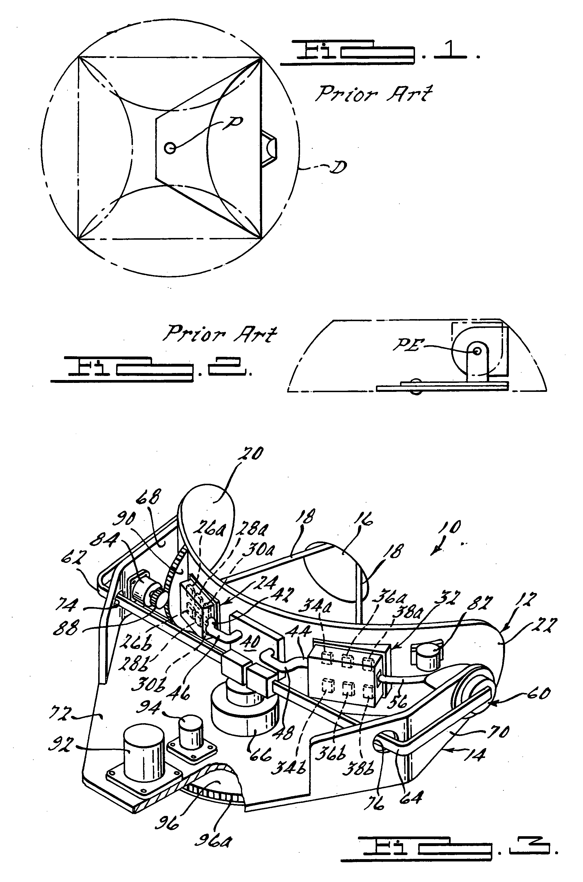
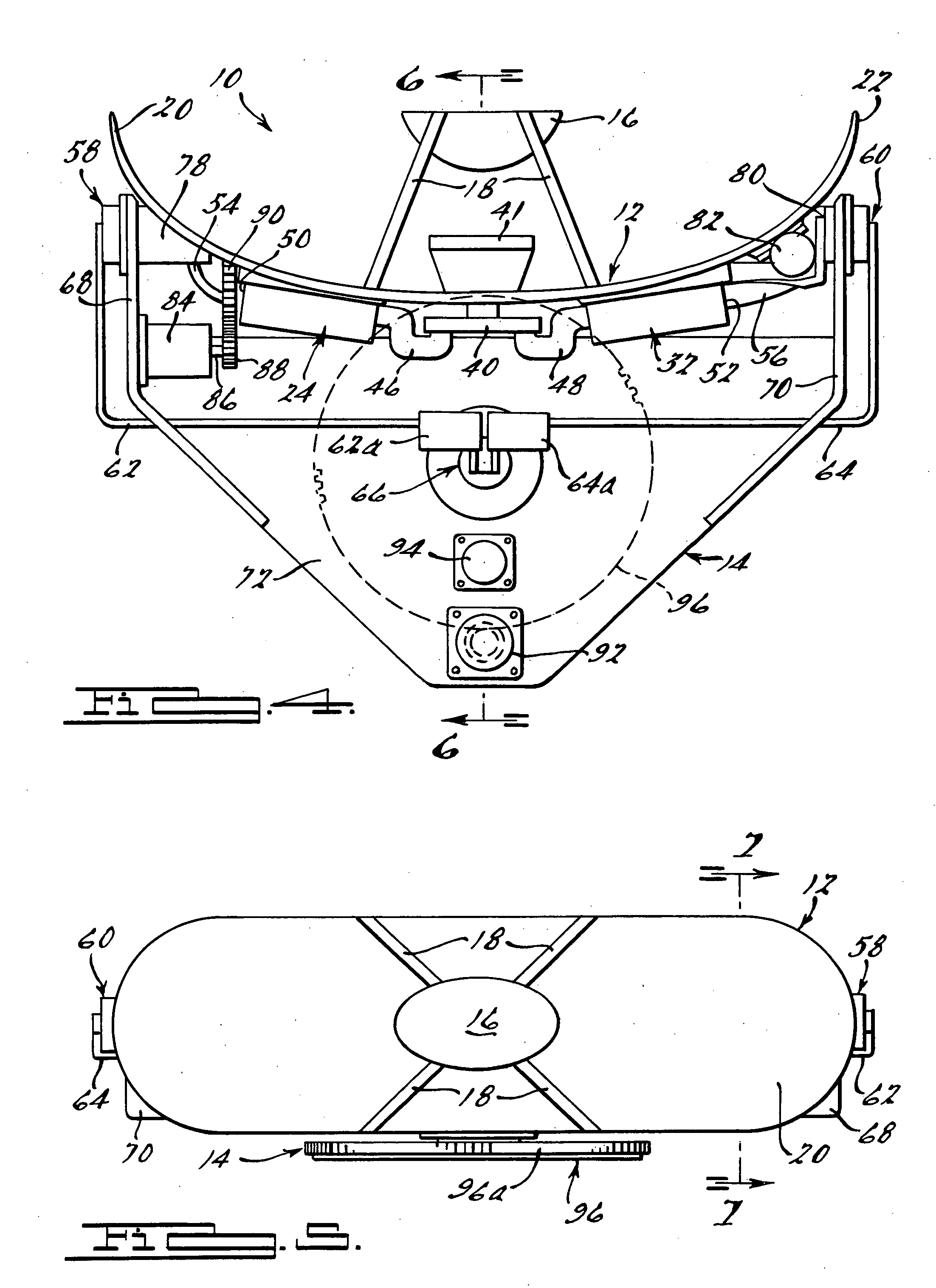
[0022] This invention relates to a mechanically scanned antenna system, preferably a Ku-band or Ka-band system, that is optimized for minimum size, weight and power. An optimized system insures the smallest swept volume, minimum structural impact and lowest RF and mechanical scanning power requirements. The optimized system is ideally suited for use on the external surfaces of smaller classes of mobile platforms such as aircraft (e.g., Boeing 737), trains and buses, as well as marine vessels. This invention also combines various features of U.S. Pat. Nos. 6,861,994, 6,642,905, 6,717,552, all of which are hereby incorporated by reference into the present application, with composite construction and small, light weight, lower power components.

[0023] Referring to FIG. 3, there is shown a mechanically scanned antenna system 10. The system 10 includes a main reflector 12 supported by a support assembly 14. The main reflector 12 includes a subreflector 16 supported by one or more struts ...


PUM


Abstract

A mechanically scanned reflector antenna system that produces a compact swept diameter and overall height, which is ideally suited for use on the external surface of a high speed mobile platform where a low profile, lightweight antenna is needed. The antenna system includes a main reflector and a subreflector both formed from composite materials. A support assembly includes a pair of arms that cantilever the main reflector forwardly of a base portion of the support assembly such that a portion of the main reflector can be positioned below an upper surface of the base portion. This enables the vertical height of the swept arc of the main reflector to be reduced when the main reflector is rotated about its elevation axis. The assembly provides an even more compact system that can be enclosed within a smaller radome when the system is employed on an external surface of a high speed mobile platform.

Description

FIELD OF THE INVENTION [0001] This invention relates to antenna apertures, and more particularly to a mechanically scanned reflector antenna apparatus that requires only a small swept volume with minimum height and weight, thus making the apparatus ideally suited for use on the external surfaces of high speed mobile platforms. BACKGROUND OF THE INVENTION [0002] With the increase in digital communications between geostationary satellites and various forms of mobile platforms, such as high speed aircraft, the need for an optimized, physically small, lightweight, low power, mechanically scanned antenna structure has grown in importance. In applications where such a mechanically scanned antenna system needs to be located on the external surface of a high speed mobile platform such as a jet aircraft, the need for a lightweight antenna system that is also compact and that can be mechanically scanned about both azimuth and elevation axes, with low power and within a small swept volume, is ...

Claims


Application Information

Patent Timeline
IPC IPC(8): H01Q13/00
CPCH01Q19/19H01Q3/08
Inventor DESARGANT, GLEN J.BIEN, ALBERT L.
Owner THE BOEING CO
Learn More