Optical connector
a technology of optical connectors and connectors, applied in the field of optical connectors, to achieve the effects of preventing connection failure, excellent reliability and safety, and suppressing light leakag
- Summary
- Abstract
- Description
- Claims
- Application Information
AI Technical Summary
Benefits of technology
Problems solved by technology
Method used
Image

Examples
first embodiment
(I) First Embodiment
(A) Optical Connector 1:
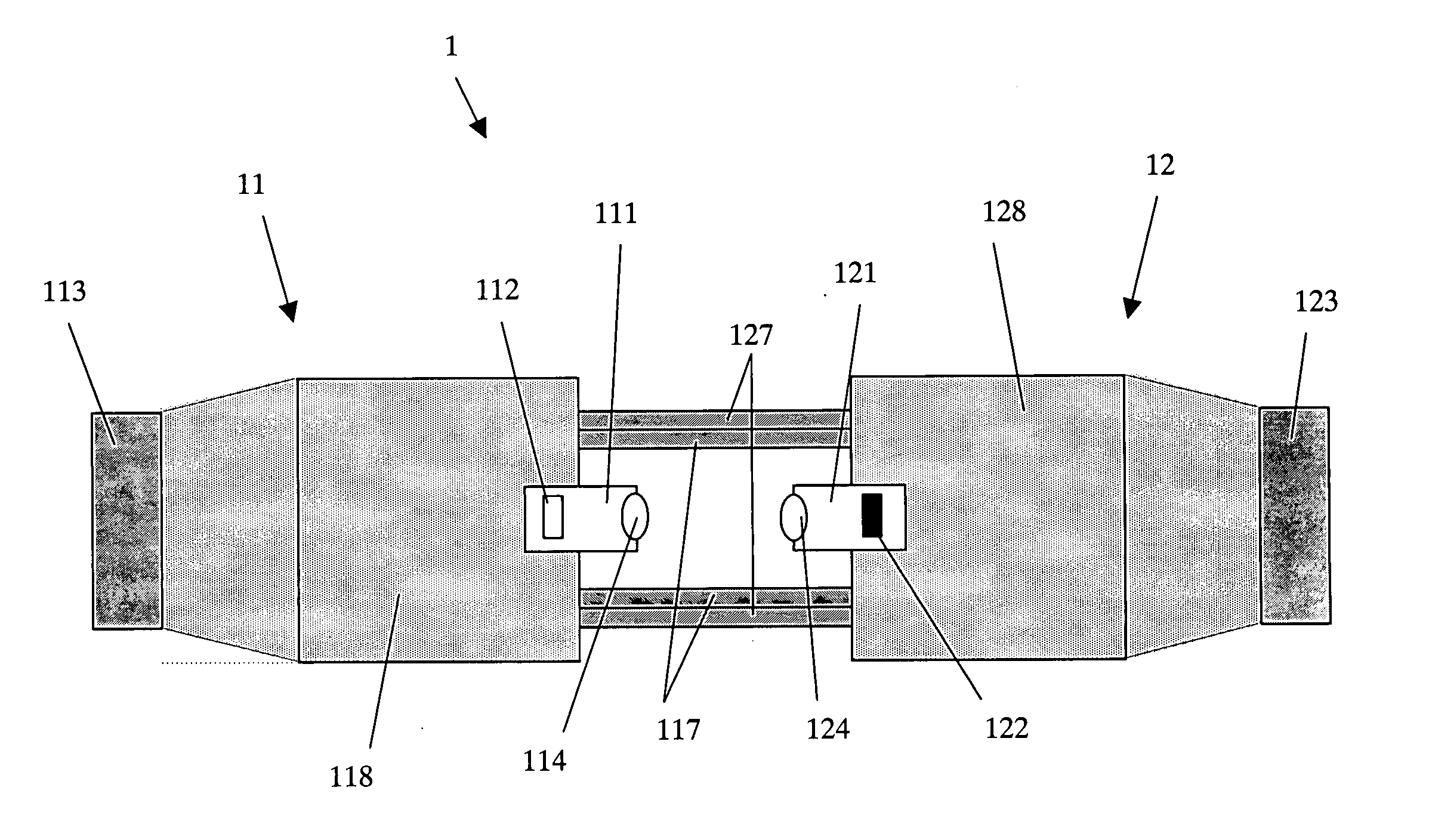
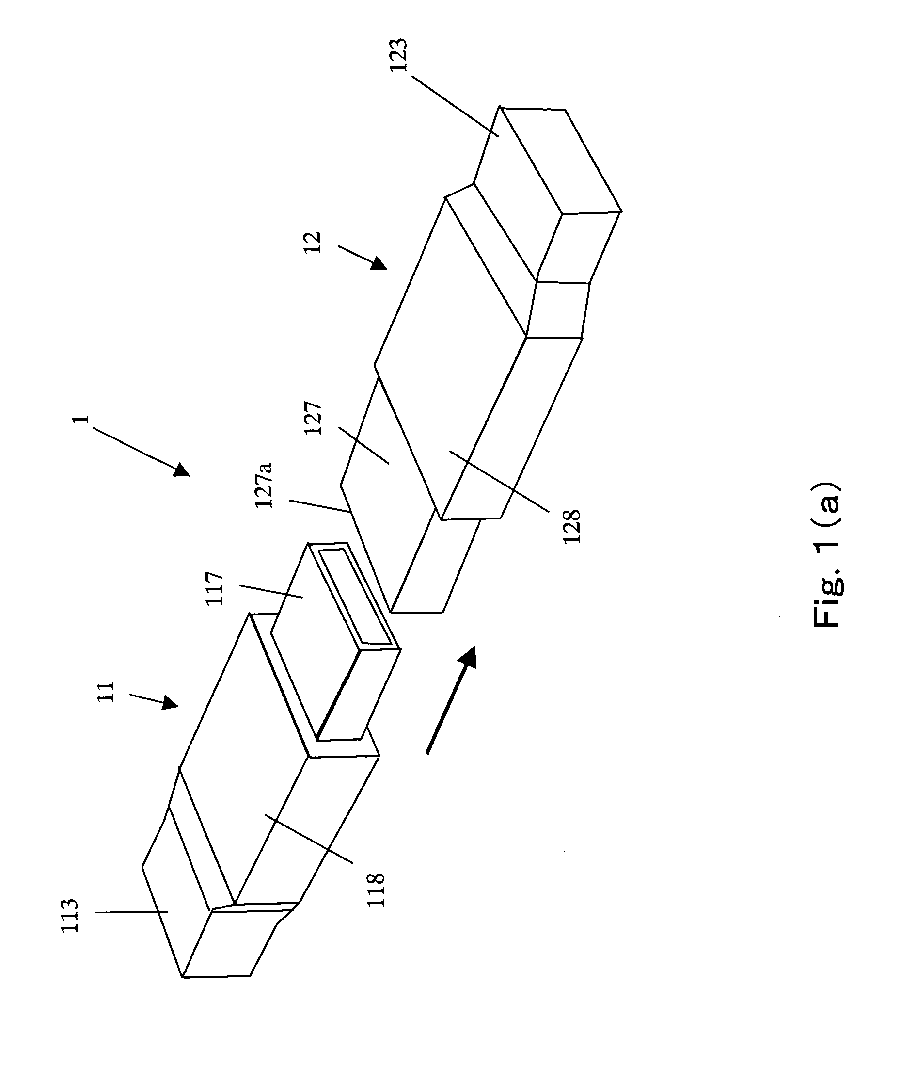
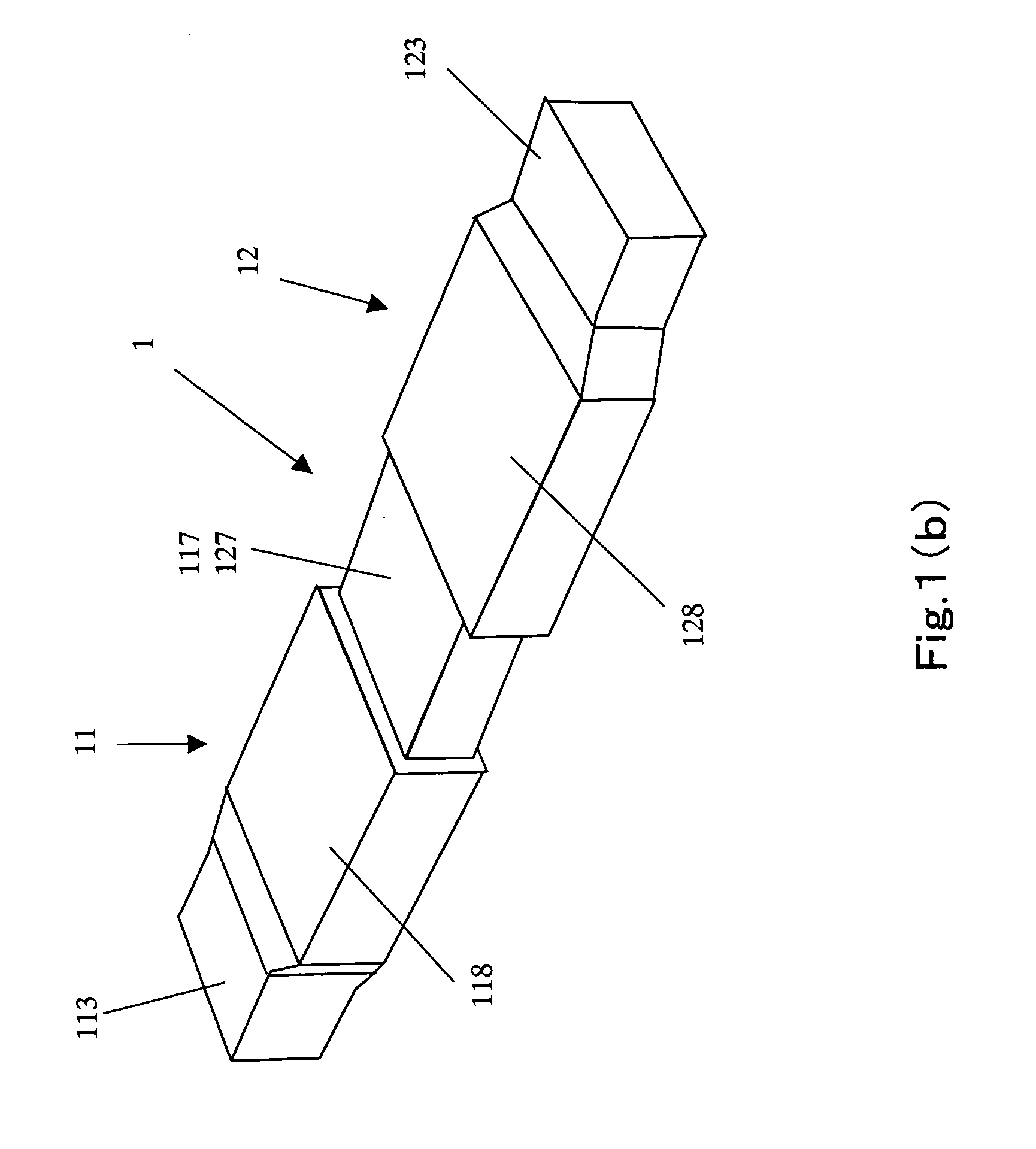
[0042]FIGS. 1A and 1B are diagrams showing an embodiment of the optical connector of the present invention, FIG. 1A is a schematic view showing a condition in which a first connector and a second connector are disconnected and FIG. 1B is a schematic view showing a condition in which the first connector and the second connector are connected.
[0043]FIG. 2 is a schematic diagram showing the structure of the interior of the case in the condition of FIG. 1B (condition in which both the connectors are connected).
[0044] The optical connector 1 of this embodiment includes a first connector 11 in which an optical transmitter module 111 is disposed inside a case 117 and a second connector 12 in which an optical receiver module 121 is disposed inside a case 127 and the first connector 11 and the second connector 12 are connectable / disconnectable as shown in FIGS. 1A and 1B. More specifically, by inserting the first connector 11 into the second co...
second embodiment
(II) Second Embodiment
[0059] The optical connector 2 according to the second embodiment of the present invention will be described with reference to FIG. 5. The optical connector 1 of the first embodiment includes the optical transmitter module 111 in the first connector 11 and the optical receiver module 121 in the second connector 12 so as to execute spatial optical transmitting in a single direction.
[0060] Contrary to this, the optical connector 2 of the embodiment includes two optical transmitter modules 111a, 111b in the first connector 11 and two optical receiver modules 121a, 121b corresponding to the optical transmitter modules 111a, 111b in the second connector 12 so as to execute plural spatial optical transmitting in a single direction (single direction multiple optical transmitting).
[0061]FIG. 5 is a schematic view showing the structure of interior of the case of the optical connector 2 according to the second embodiment. The optical connector 2 of this embodiment incl...
third embodiment
(III) Third Embodiment
[0067] The optical connector 3 according to the third embodiment of the present invention will be described with reference to FIG. 6. The optical connector 3 of this embodiment includes an optical transmitter module 111c and an optical receiver module 121d in the first connector 11 and an optical transmitter module 111d and an optical receiver module 121c in the second connector 12 so as to transmit optical signals in spatial bi-directions.
[0068] Like reference numerals are attached to the same or substantially the same components as described previously in a following description and explanation of those components is not described.
[0069]FIG. 6 is a schematic view showing the structure of interior of the case of the optical connector 3 of the third embodiment. In the optical connector 3 of this embodiment, the optical transmitter module 111c disposed in the first connector 11 and the optical receiver module 121c disposed in the second connector 12 are oppose...
PUM
 Abstract
Description
Claims
Application Information
 - R&D
- Intellectual Property
- Life Sciences
- Materials
- Tech Scout
- Unparalleled Data Quality
- Higher Quality Content
- 60% Fewer Hallucinations
Browse by: Latest US Patents, China's latest patents, Technical Efficacy Thesaurus, Application Domain, Technology Topic, Popular Technical Reports.
© 2025 PatSnap. All rights reserved.Legal|Privacy policy|Modern Slavery Act Transparency Statement|Sitemap|About US| Contact US: help@patsnap.com