Drill fixture

a technology of drill fixture and drill bit, which is applied in the direction of drilling/boring measurement device, manufacturing tools, metal-working machine components, etc., can solve the problems of not providing adequate control of the displacement of the drill bit toward the surface, cumbersome assembly and operation, and unsuitable for us

Active Publication Date: 2006-11-23
SMARTOOLS
View PDF28 Cites 6 Cited by
  • Summary
  • Abstract
  • Description
  • Claims
  • Application Information

AI Technical Summary

Benefits of technology

[0008] The drill fixture is particularly adapted for use in drilling holes in surfaces which are difficult to access such as a vehicle frame. In such an environment, an opposite portion of the vehicle frame may serve as the rear surface. If a rear surface is not readily available, a mounting bracket is provided for connection with the vehicle and has a surface parallel to and opposite a surface of the vehicle frame to be drilled.

Problems solved by technology

While the prior devices operate satisfactorily, they do not provide adequate control of displacement of the drill toward the surface to be drilled.
Moreover, they are cumbersome to assemble and operate, and thus are not suitable for use in tight environments with limited access to the drilling site.

Method used


Image

  • Drill fixture
  • Drill fixture
  • Drill fixture

Examples


Embodiment Construction

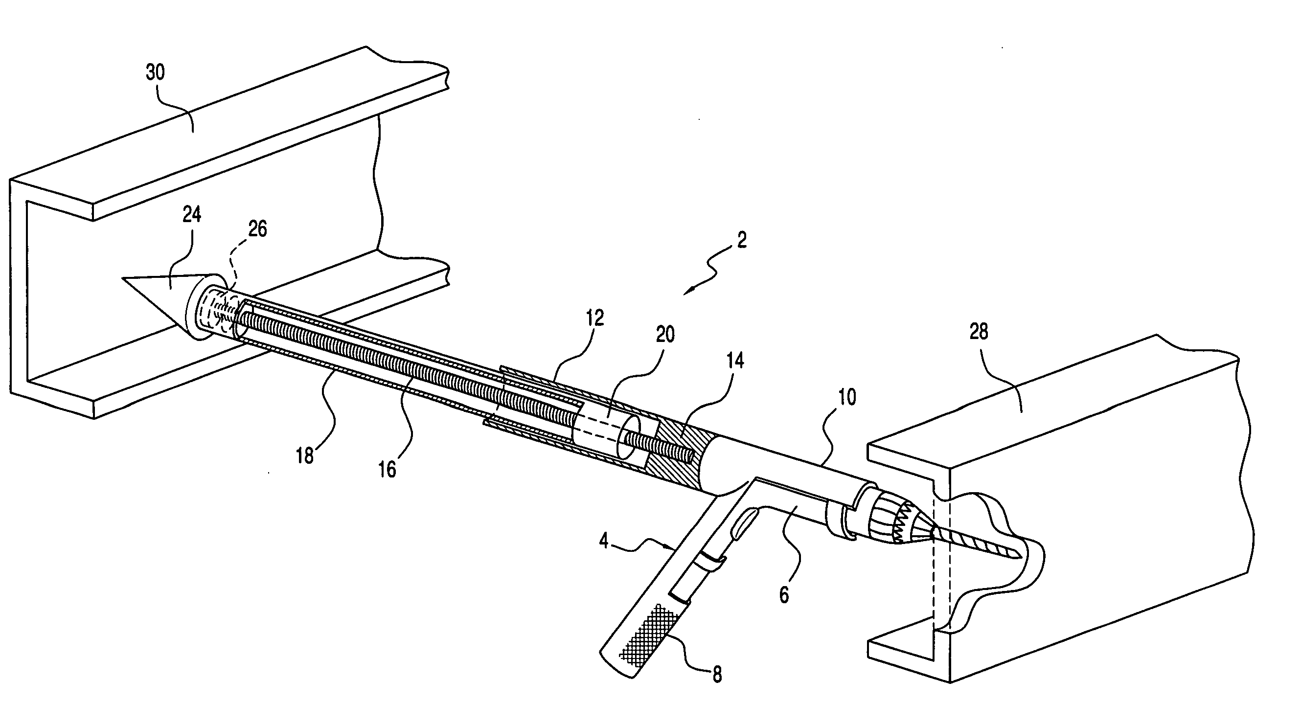
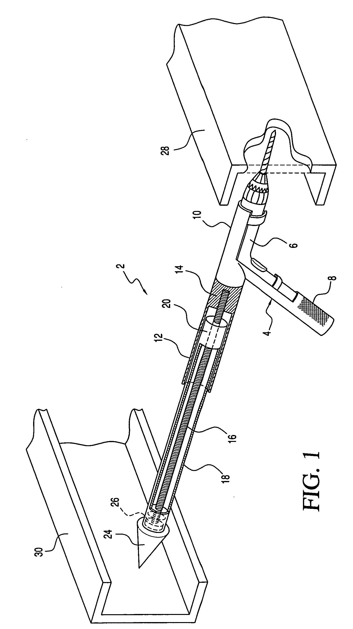
[0021] Referring first to FIG. 1, the drill fixture 2 according to a preferred embodiment will be described. The fixture includes a housing 4 configured to receive a power drill 6. It will be readily apparent that differently configured housings may be provided for receiving differently configured drills. In each configuration, the housing includes a handle 8, a forward portion 10 from which the drill bit portion of the drill 6 protrudes, and a rearwardly extending cylindrical section 12.

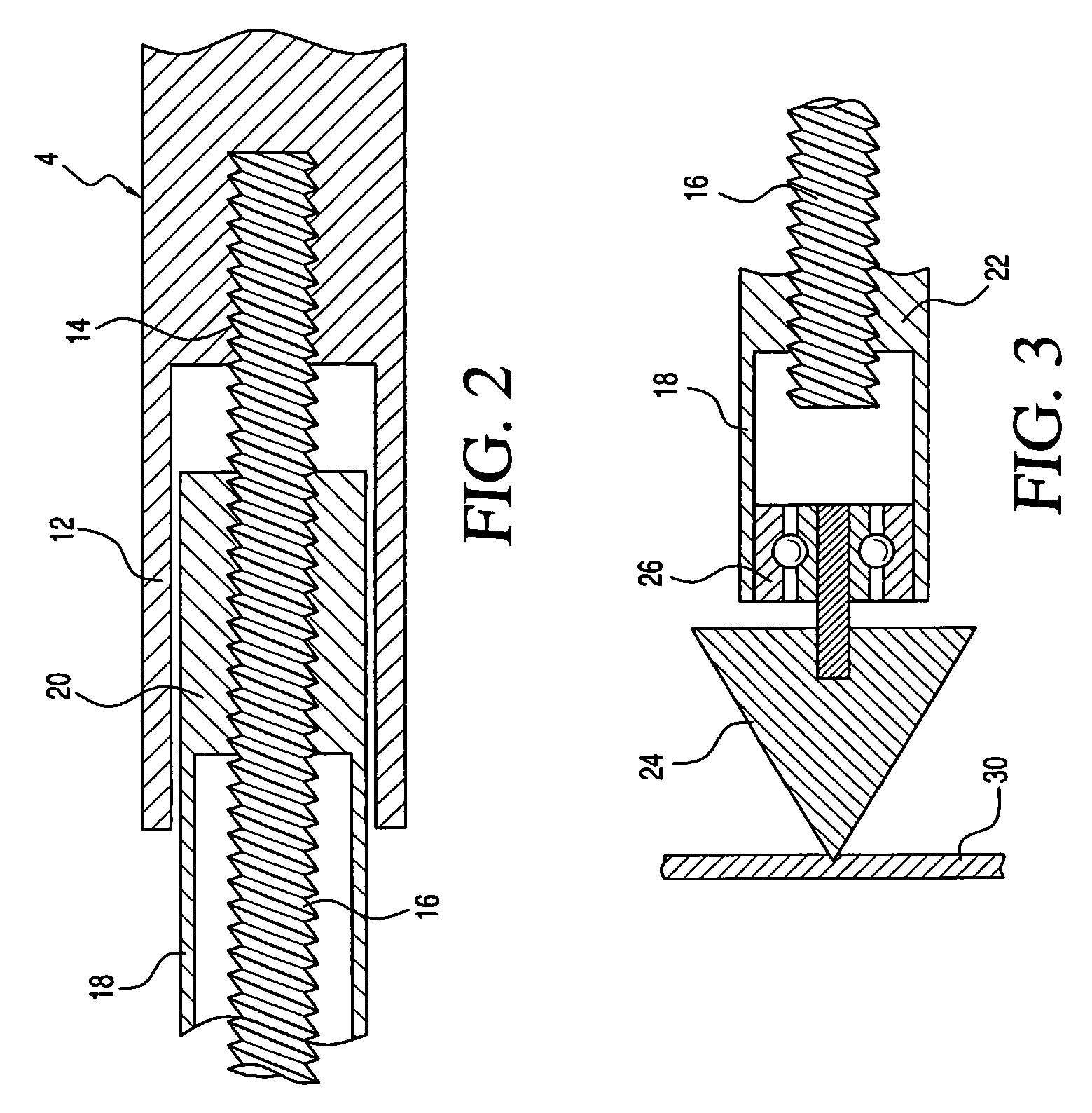
[0022] As shown in detail in FIG. 2, the housing contains a threaded opening 14 for receiving a threaded rod 16. In a preferred embodiment, the rod is fixed relative to the housing. The rod extends rearwardly from the housing and extends beyond the end of the rearwardly extending cylindrical portion 12 of the housing as shown in FIG. 1. A cylindrical or tubular sleeve 18 is threadably connected with the threaded rod 16 for displacement along the length of the rod. The sleeve includes a forward inte...


PUM

PropertyMeasurementUnit
displacementaaaaaaaaaa
lengthaaaaaaaaaa
drilling forceaaaaaaaaaa

Abstract

A drill fixture enabling drilling through hard objects in a confined area includes a housing, a threaded rod connected with the housing, and a tubular adjustment sleeve rotatably connected with the rod. A drill is arranged in the housing and has a drill bit extending in a forward direction. The sleeve is rotated relative the threaded rod for displacement along the length of the rod until the sleeve engages a fixed surface opposite the object to be drilled. With the sleeve rear portion engaging the fixed surface, further rotation of the sleeve displaces the housing in a forward direction during rotation of the drill bit so that the bit bores through the hard object until a hole is formed. Rotation of the sleeve in the opposite direction causes the drill bit to be retracted from the object. In lieu of a rotatable sleeve, a piston may be provided which is extended and retracted relative to the housing to provide a linear drilling force to the drill bit relative to a fixed surface.

Description

[0001] This application is a continuation-in-part of application Ser. No. 11 / 132,847 filed May 19, 2005, now abandoned.BACKGROUND OF THE INVENTION [0002] When it is necessary to drill through hard surfaces, it is often difficult to apply sufficient force to the drill in the drilling direction so that the drill bit can bore through the surface. For example, in the repair of large vehicles such as trucks, it is often necessary to drill through the metal truck frame. Because access to the frame is limited, it is difficult to position the drill and apply sufficient force to the drill during the drilling operation. The present invention relates to a drill fixture which holds and advances the drill toward the surface to be drilled. BRIEF DESCRIPTION OF THE PRIOR ART [0003] Drill fixtures are well-known in the patented prior art as evidenced by the U.S. Pat. to Pine No. 2,947,204 which discloses a universal power tool holder in which an inner telescoping member slides vertically within a s...

Claims


Application Information

Patent Timeline
Patent Type & Authority Applications(United States)
IPC IPC(8): B23B47/00
CPCB25H1/0064Y10T408/5628Y10T408/68Y10T408/5626Y10T408/6793
Inventor KOPP, JAMES KENNETH
Owner SMARTOOLS
Why Eureka
Try Eureka