Thread-thru polyaxial pedicle screw system

a technology of pedicles and threads, applied in the field of threads, can solve the problems of locking pins, difficult for surgeons to grasp in the midst of surgery, lack of stabilized angular placement positions during installation, etc., and achieve the effect of lowering inventory costs

Active Publication Date: 2011-05-17
ORTHO INNOVATIONS
View PDF441 Cites 71 Cited by
  • Summary
  • Abstract
  • Description
  • Claims
  • Application Information

AI Technical Summary

Benefits of technology

The present invention is a polyaxial pedicle screw system that permits the threads of a pedicle screw to pass thru a lower section of a connecting member during manufacturing. The pass thru design permits the manufacturer to use a range of different size shanks and threads while using a common connector member thereby lowering inventory costs and providing the surgeon with a similar shaped connector despite the type of pedicle screw employed. The system includes a means for applying tension to the pedicle screw anchoring member to assist in surgery.
The polyaxial bone screw has a threaded shank extending outwardly from a spherical ball for use in anchoring to the spine and a connector member that includes a socket constructed and arranged to accept the spherical ball. In the disclosed embodiment, the connector member is illustrated as a U-shaped connector member having a lower receptacle that operates as a socket for housing a retainer ring. The socket is receptive to the spherical ball which is inserted through the top of the connector during a manufacturing step. The retainer ring is spring loaded against a upper component of the connector member and engages the spherical ball so as to keep the U-shaped connector member in position during installation. A surgeon can easily move the connector member into a preferred position and the springs keep sufficient tension on the retainer ring so as to maintain the connector in position. This facilitates the installation of the rod as the U-shaped connector not only can be rotated into a position for proper placement of the connecting rod but the proper angle of the saddle can also maintained allowing the surgeon to align additional screws for ease of rod placement, and bend the rod as needed to align for any office anchoring.
Accordingly, it is an objective of the present invention to teach the use of a polyaxial pedicle screw system for posterior fixation having a common connector for use with different sized shanks and thread types, which lowers inventory requirements and provides the surgeon with a uniform connector.
It is another objective of the present invention to teach the use of a polyaxial pedicle screw having a biasing member to apply a force between the anchoring member and the connector member, the force facilitates installation by maintaining the connector component in an angular placement position as desired by the surgeon.
It is another objective of the present invention to teach the use of a polyaxial bone screw assembly having a thicker connector even when oversized anchoring screws are employed by use of a thread thru design of a lower connector, the upper connector need not be threaded providing a greater safety factor when a set screw fastener is employed by avoiding splaying.
It is yet another objective of the present invention to provide a simple spinal fixation system having only a few components for use in assembly and limiting component parts needed during assembly by use of a common connector.

Problems solved by technology

However, one of the problems with a polyaxial pedicle screw is the lack of a stabilized angular placement position during installation.
Once a polyaxial pedicle screw is inserted into the bone, the connector component portion has yet to receive a connecting rod leaving the connector assembly to flop over making it difficult for the Surgeon to grasp while in the midst of surgery.
This problem is compounded by the need to align multiple component heads for receipt of a connecting rod.
Another problem with the prior art is the inability to use various size anchoring screw in combination with a common saddle larger saddle, both of which leads to assembly integrity over a large range of installation considerations.
A problem with the screw is the need for the locking pin and the inability of the base screw to accommodate a threaded extension bolt.

Method used


Image

  • Thread-thru polyaxial pedicle screw system
  • Thread-thru polyaxial pedicle screw system
  • Thread-thru polyaxial pedicle screw system

Examples


Embodiment Construction

While the present invention is susceptible of embodiment in various forms, there is shown in the drawings and will hereinafter be described a presently preferred embodiment with the understanding that the present disclosure is to be considered an exemplification of the invention and is not intended to limit the invention to the specific embodiments illustrated.

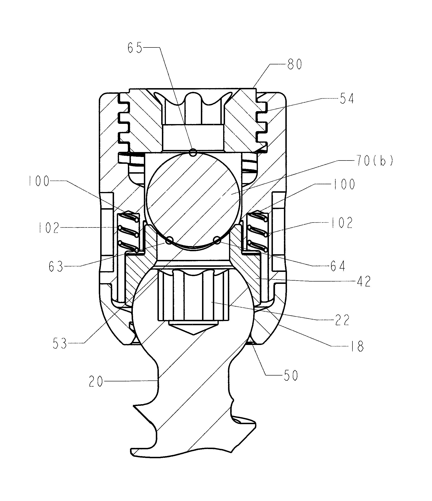
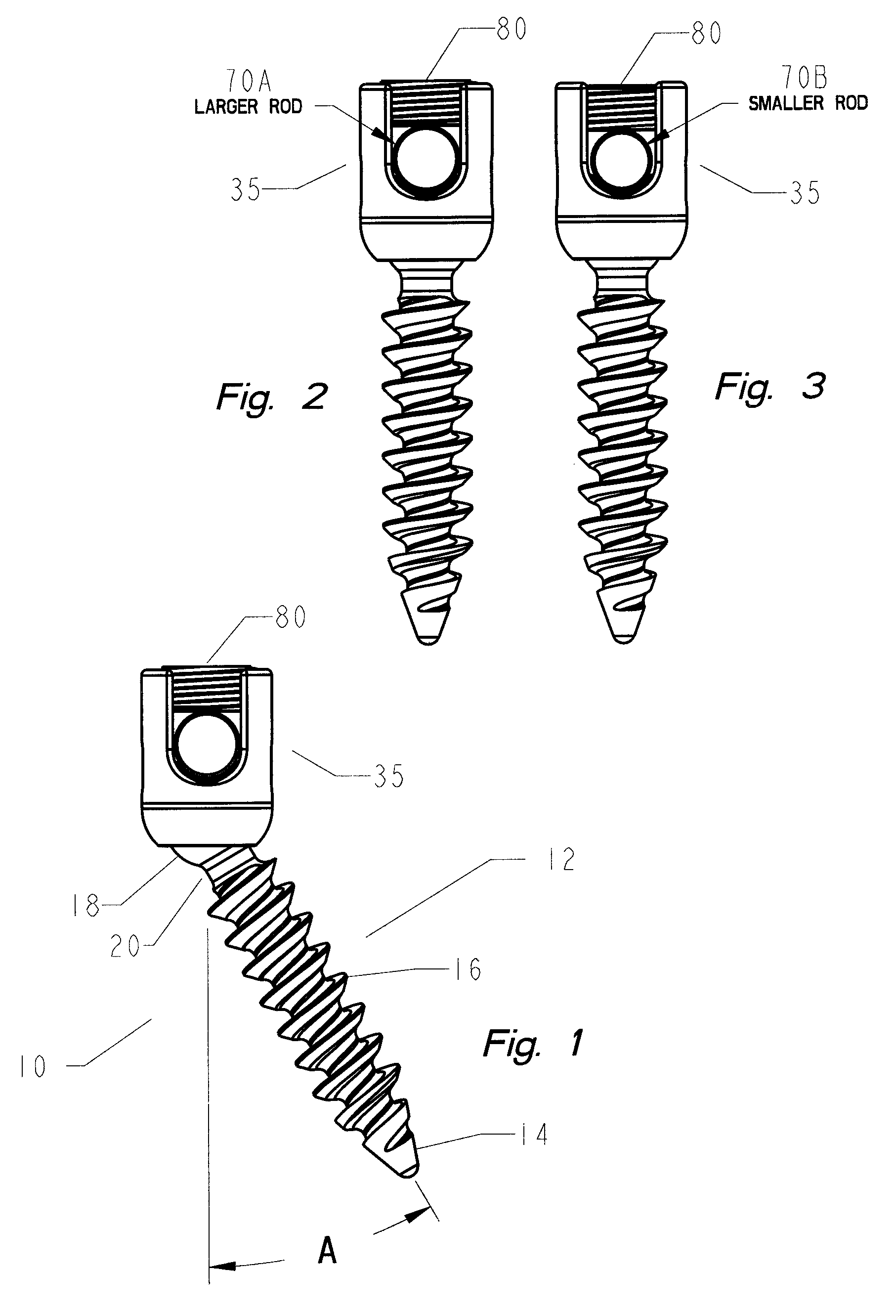
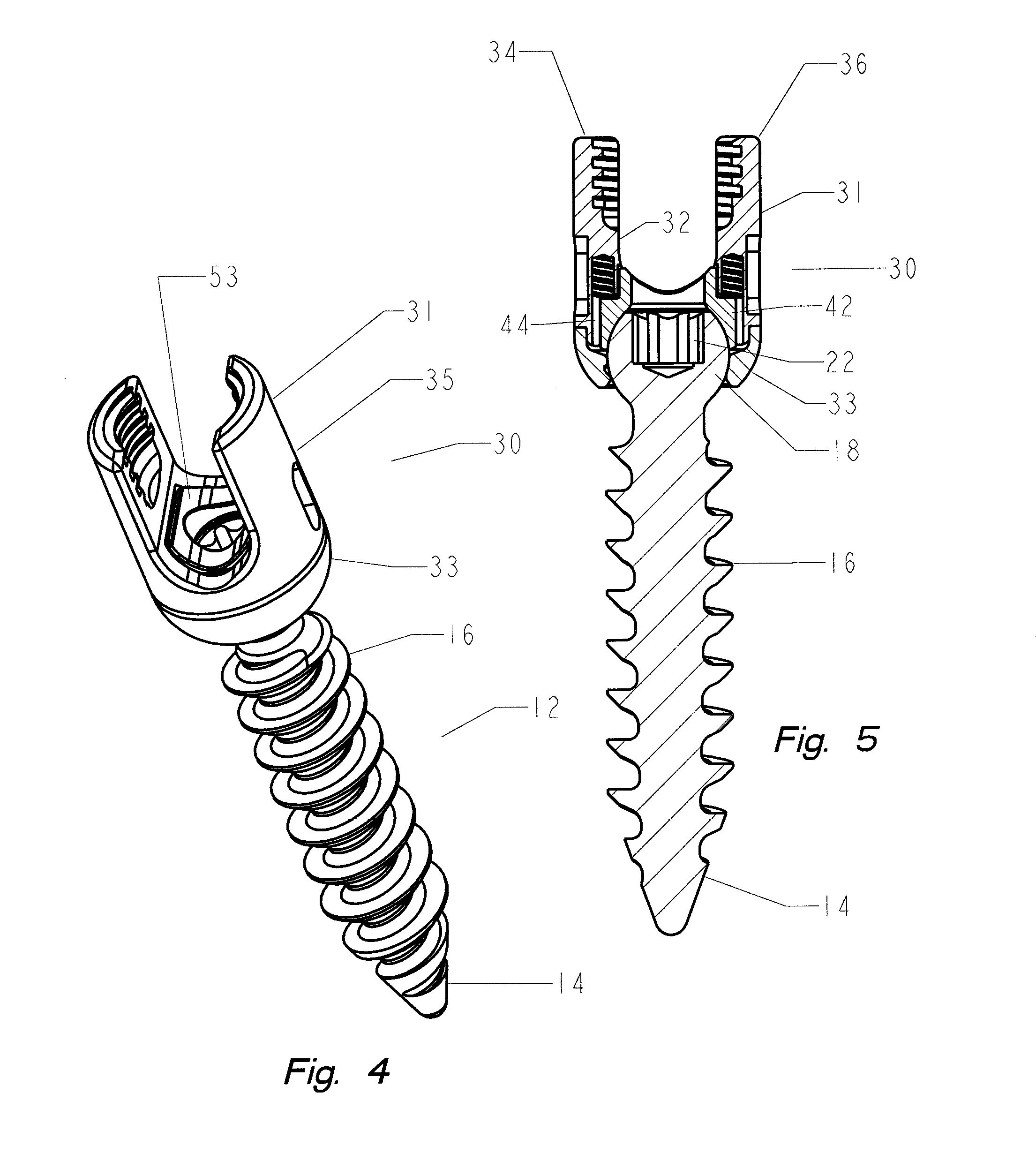
Referring generally to the Figures, disclosed is an exemplary embodiment of the thread thru polyaxial pedicle screw system for use in a spinal fixation system. The thread-thru pedicle screw system (10) is based on an anchoring member formed from a bone screw (12) including a shank (14) with at least one helical thread (16) formed along the length thereof. It is important to note that the proportions of the bone screw depicted are for illustrative purposes only and variations in the length of the shank, diameter of the screw, thread pitch, thread length, number of thread leads, shank induced compression and the like may be vari...


PUM


Abstract

A thread-thru polyaxial pedicle screw fastening system. The fastening system consists of an anchoring bone screw having threads on one end for use in anchoring to the screw to the spine and a spherical connector on the other end operating as a pivot point about which a U-shaped connecting assembly moves in a polyaxial fashion. The U-shaped connecting assembly, for receipt of a spinal connecting rod, has a biased retainer ring for maintaining a positive tension between the connecting assembly and the anchored screw. The system allows for an improved manufacturing step wherein the threaded shank of a bone screws can be passed through a lower portion of the connecting assembly allowing a variety of bone screw sizes to be used with a common sized connector.

Description

CROSS REFERENCE TO RELATED APPLICATIONSThis application is related to U.S. patent application Ser. No. 12 / 355,145 filed Jan. 16, 2009 which claims the benefit of the filing date of U.S. Provisional Patent Application No. 61 / 114,515 filed on Nov. 14, 2008; and U.S. patent application Ser. No. 11 / 749,615 filed May 16, 2007 the contents of these applications are herein incorporated by reference.FIELD OF THE INVENTIONThis invention is directed to the field of pedicle screws, and in particular, to a thread-thru polyaxial pedicle screw system adapted for use as a spinal implant.BACKGROUND OF THE INVENTIONThe use of pedicle screw fasteners is well known for their use with spinal fixation systems. In the field of spinal pathologies, spinal fixation systems represent a major medical breakthrough. Surgically implanted fixation systems are commonly used to correct a variety of back structure problems, including those which occur as a result of trauma or improper development during growth. A co...

Claims


Application Information

Patent Timeline
Patent Type & Authority Patents(United States)
IPC IPC(8): A61B17/70
CPCA61B17/7037A61B17/7032
Inventor HAMMILL, SR., JOHN E.DOUBLER, ROBERT L.
Owner ORTHO INNOVATIONS
Why Eureka
Try Eureka