Controlled flow microfluidic device and method of fabrication

a microfluidic device and controlled flow technology, applied in the field of controlled flow microfluidic devices and methods of fabrication, can solve the problems of difficult fabrication of reproducible microfluidic devices, difficult to predict and correlate fluid flow with modeled fluid flow analysis, and difficult to manufactur

Inactive Publication Date: 2006-11-23
LEVINE LEANNA M +1
View PDF8 Cites 13 Cited by
  • Summary
  • Abstract
  • Description
  • Claims
  • Application Information

AI Technical Summary

Problems solved by technology

In prior art devices, fluid flow can be difficult to predict and correlate with modeled fluid flow analysis.
Accordingly, reproducible microfluidic devices, suitable for use in a commercial, mass production, laboratory setting, are difficult to fabricate.

Method used


Image

  • Controlled flow microfluidic device and method of fabrication
  • Controlled flow microfluidic device and method of fabrication
  • Controlled flow microfluidic device and method of fabrication

Examples


Embodiment Construction

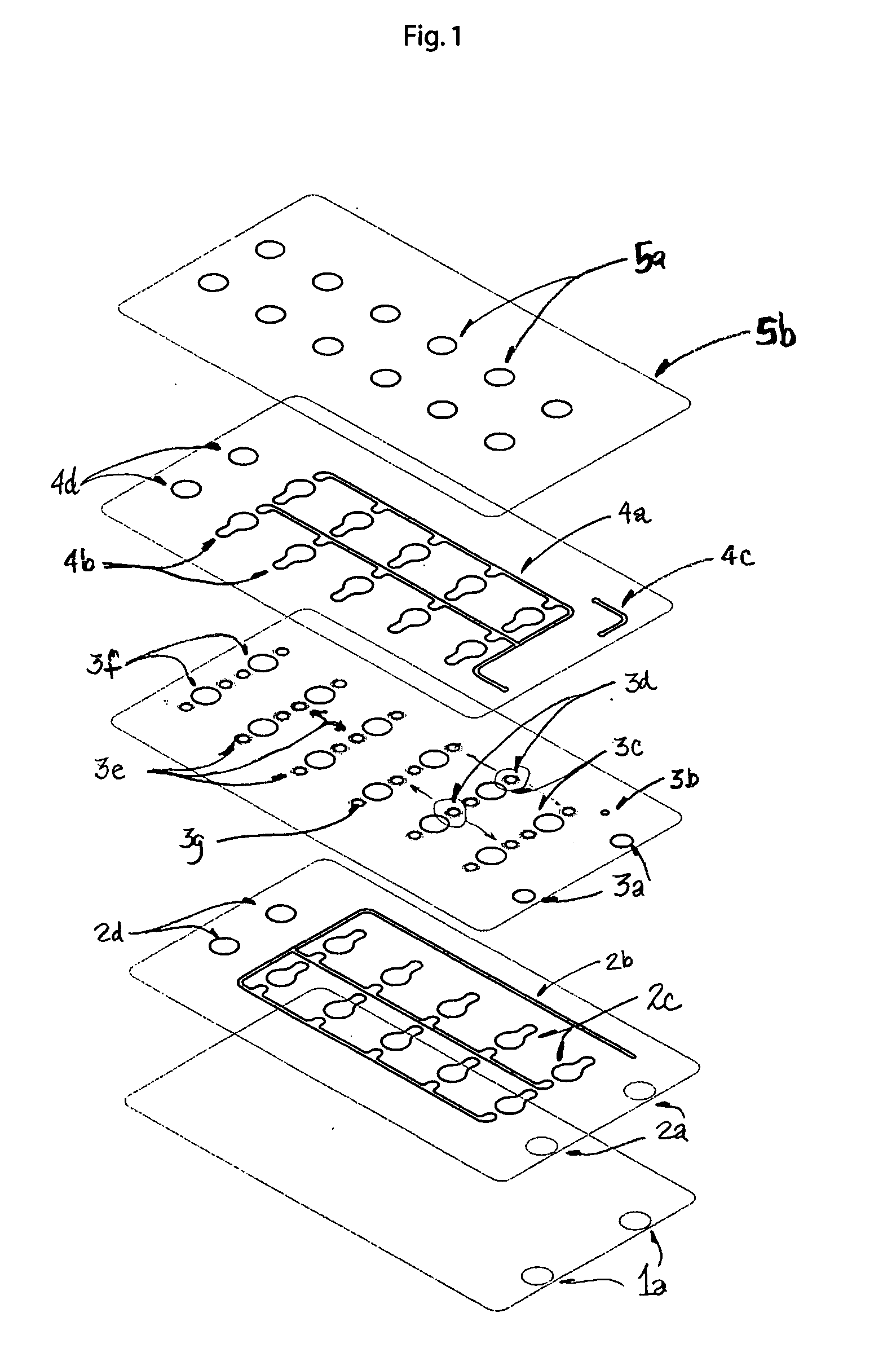
[0009] The invention is based on the realization that undesirable changes in fluid flow in a device can be made negligible by introducing into the fluidic network a system of fixed resistances that are greater than the fluid pathway resistances in the device due to the surface properties and geometry of the flow channels.

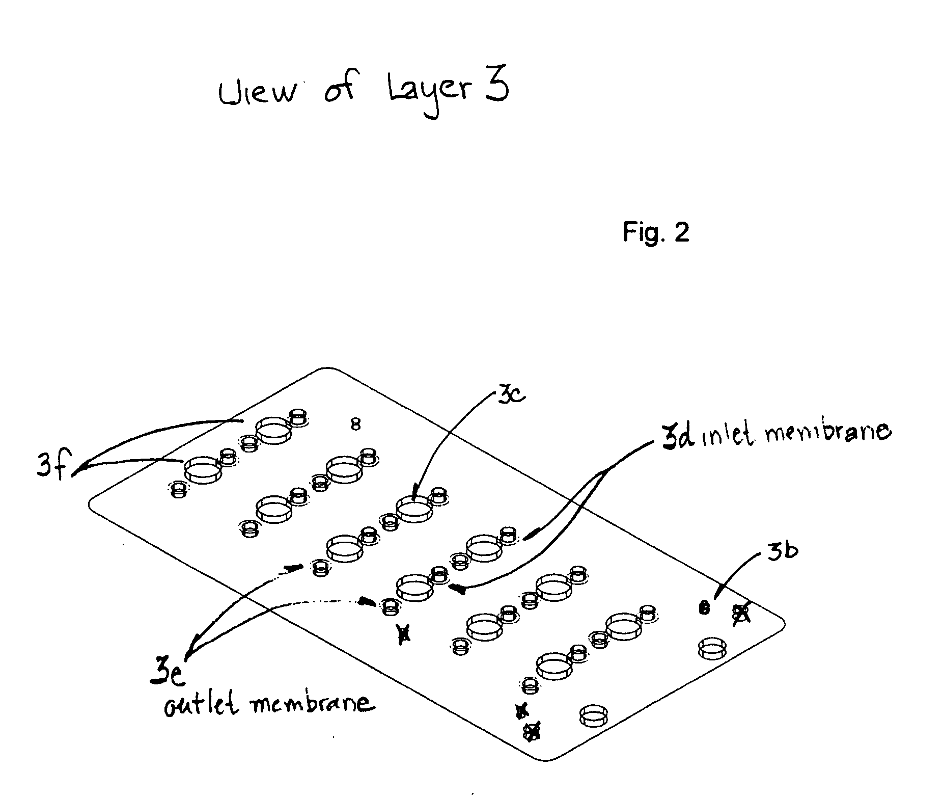
[0010] By placing selected resistances at the inlets, outlets and branches of the flow channels, the same principles that apply to electronic circuit design can be applied to the development of fluidic flow paths where fractional flows in various fluid paths are controlled by the placement of resistive elements. In the embodiments of the invention, porous membranes are employed as resistive elements and such membranes can be used with or without fixed diameter constrictions or vias, to connect one part of a device to another.

[0011] The flow in these devices can be modeled using Navier-Stokes flow in which the fluid movement and pressure drops in the system are dep...


PUM

PropertyMeasurementUnit
porosityaaaaaaaaaa
surface areaaaaaaaaaaa
resistanceaaaaaaaaaa

Abstract

The invention comprises a method and device for cell culture analysis using microporous membranes to control fluid flow in a device. The microporous membranes are of defined porosity and surface area to effectively increase the fluidic circuit resistance and control fluid flow through the device.

Description

CROSS REFERENCE TO RELATED APPLICATIONS [0001] The present application claims the benefit of priority of Provisional Patent Application Ser. No. 60 / 683,103 filed May 21, 2005 for Leanna M. Levine et al, the entire content of which is incorporated herein by reference.FIELD OF THE INVENTION [0002] The invention comprises a device and method for cell culture analysis using microporous membranes to control fluid flow in the device. BACKGROUND OF THE INVENTION [0003] In prior art devices, fluid flow can be difficult to predict and correlate with modeled fluid flow analysis. Flow rates in a device are affected, for example, by changes in the device orientation due to gravitational forces, non-homogeneous surface characteristics of material along the length of the fluidic channels and the general surface material properties of the device related to a specimen contact angle. Accordingly, reproducible microfluidic devices, suitable for use in a commercial, mass production, laboratory setting...

Claims


Application Information

Patent Timeline
Patent Type & Authority Applications(United States)
IPC IPC(8): C12M1/34
CPCB01D61/18B01D2325/028B01L3/502707B01L3/502746B01L2300/0816C12M41/00B01L2400/0487B01L2400/084C12M23/12C12M23/16C12M29/04B01L2300/0887
Inventor LEVINE, LEANNA M.RICCO, ANTONIO J.
Owner LEVINE LEANNA M
Why Eureka
Try Eureka