Protective thin film dressing for therapeutic and diagnostic ultrasound

a technology of therapeutic ultrasound and protective film, applied in the field of protective film dressing, can solve the problems of sensitive instruments, high cost of transducers, and increased risk of dropping fragile probes, and deliver therapeutic treatments that provide little protection against contamination

Inactive Publication Date: 2006-11-23
WENDELKEN MARTIN EDMUND +2
View PDF10 Cites 41 Cited by
  • Summary
  • Abstract
  • Description
  • Claims
  • Application Information

AI Technical Summary

Benefits of technology

[0009] The present invention provides a protective thin film dressing which has a number of advantages over prior art.
[0010] A principal objective of this invention is to provide a dressing to seal the external surface of a transducer which comes in contact with a body.
[0011] Another objective is to provide a thin film dressing that allows unimpeded transmission of ultrasound waves through the film dressing.
[0012] Still anothe

Problems solved by technology

Transducers are expensive, sophisticated, delicate instruments that employ fragile piezoelectric crystals to generate ultrasound waves.
Many manufacturers warn of possible damage to the transducer and instruct to avoid using most cleaning solutions available.
Present cleaning methods of ultrasound transducers used to acquiring diagnostic images or deliver therapeutic treatments provide little protection against contaminated probes.
Also, using a sheath to cover a transducer is cumbersome and slippery which greatly increases the risk of dropping a fragile probe.
In addition, sterile sheaths are expensive to use.
The application of a sheath over a transducer using Smith's doubled sided adhesive hydrogel membrane increased the probability of the cover sticking to the side making it difficult to apply.
The cost of designing and manufacturing custom molded standoffs are expensive because standoff pads can only be used on the probe that it was designed for.
Previous art fails to discuss decontamination of such devices.
The disposable standoff

Method used


Image

  • Protective thin film dressing for therapeutic and diagnostic ultrasound
  • Protective thin film dressing for therapeutic and diagnostic ultrasound
  • Protective thin film dressing for therapeutic and diagnostic ultrasound

Examples


Embodiment Construction

—FIGS. 1 to 10

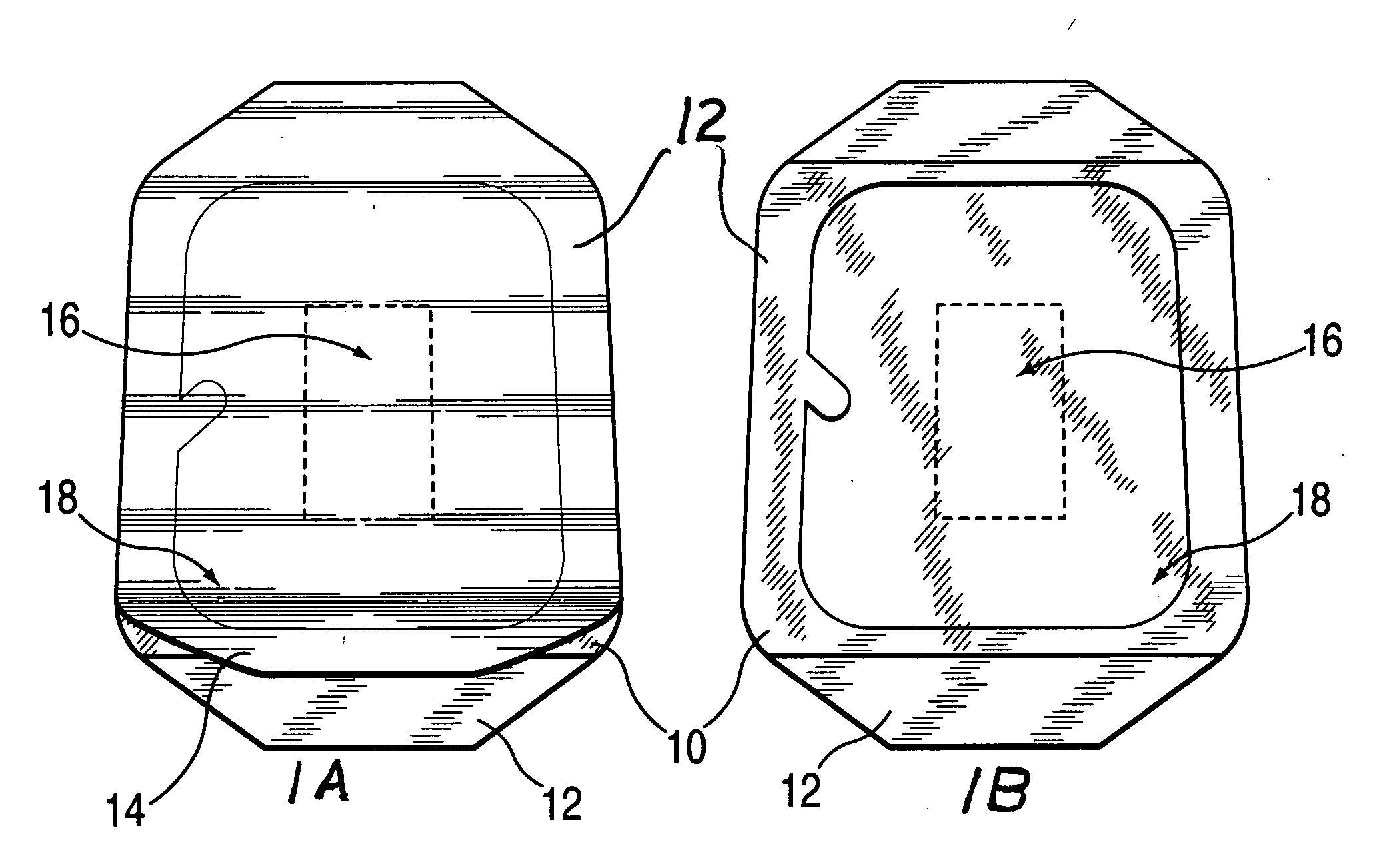
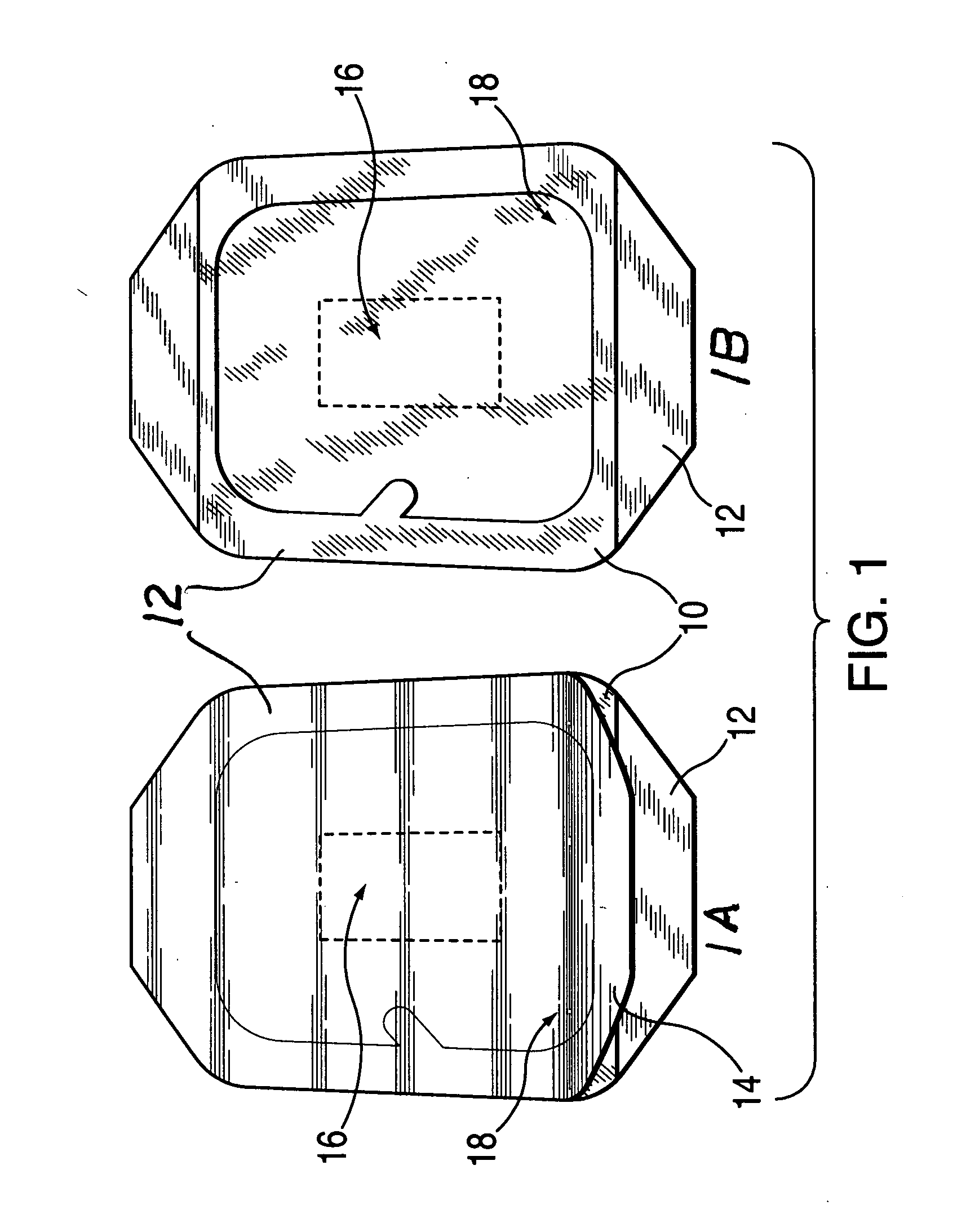
[0035] Directing attention to FIG. 1 of the drawings, two images of a thin film dressing 10 are illustrated. Thin film dressing 10 is typically transparent in nature and normally encased in an outer packaging to keep thin film dressing 10 sterile. FIG. 1 shows two images of thin film dressing 10 both of which have the outer packaging removed. Thin film dressing 10 has two surfaces. In FIG. 1a, thin film dressing 10 shows a support frame 12 on the outer surface and a film backing layer 14 covering the opposite surface. The purpose of film backing layer 14 is to provide protection to an adhesive area 18 applied on the outer edges on one surface of thin film dressing 10. Thin film dressings 10 are extremely thin (ranging in microns) and are very flexible. Support frame 12 provides assistance during application and allows for easy handling. Support fame 12 helps reducing unwanted folding of thin film dressing 10 when thin film dressing 10 is applied to various surfaces.

[0...


PUM


Abstract

A protective thin film adhesive dressing 10 is disclosed for use during diagnostic ultrasound exams and therapeutic ultrasound treatments. Thin film dressing 10 accommodates and covers various shaped transducers 22 and provides a sterile contact surface between a transducer's acoustic window 24 and a body 34, human or animal. Thin film dressing 10 is transparent, ultra light weight and does not change the shape or dimensions of an ultrasound probe 22 during use. Ultrasound wave freely traverse thin film dressing 10 without have a contact media such a gel 20 between acoustic window 24 and the inner surface of thin film dressing 10.

Description

1. FIELD OF THE INVENTION [0001] This patent relates to the use of a protective thin film dressing during both diagnostic ultrasound applications and therapeutic ultrasound treatments. 2. BRIEF DESCRIPTION OF PRIOR ART AND BACKGROUND OF THE INVENTION [0002] In medicine, diagnostic ultrasound has become one of the most utilized imaging methods used to diagnose and monitor a great number of medical conditions. In addition, ultrasound is also utilized for therapeutic conditions. Both diagnostic and therapeutic applications employ a transducer (ultrasound probe) which generates and sends ultrasound waves into a body. It is well established that air is a poor conductor of ultrasound waves. When utilizing either diagnostic, therapeutic, or a combination of both modalities of ultrasound, a contact media is placed between a transducer and a body. This contact media, usually in the form of a gel or a standoff pad, couples a transducer and a physical surface of a body. Once coupled, the gel s...

Claims


Application Information

Patent Timeline
IPC IPC(8): A61B8/00A61H1/00
CPCA61B8/4281A61H23/0245A61B8/4422
Inventor WENDELKEN, MARTIN EDMUNDPOPE, CHARLES L.ROSENBAUM, HOWARD S.
Owner WENDELKEN MARTIN EDMUND
Why Eureka
Try Eureka