Dynamic damping element for two bones

Active Publication Date: 2006-11-23
SYNTHES USA
View PDF27 Cites 130 Cited by
  • Summary
  • Abstract
  • Description
  • Claims
  • Application Information

AI Technical Summary

Problems solved by technology

A disadvantage of this known damping element is that the spring characteristics of the middle, elastic part is determined by the geometry and the choice of material.

Method used


Image

  • Dynamic damping element for two bones
  • Dynamic damping element for two bones
  • Dynamic damping element for two bones

Examples


Embodiment Construction

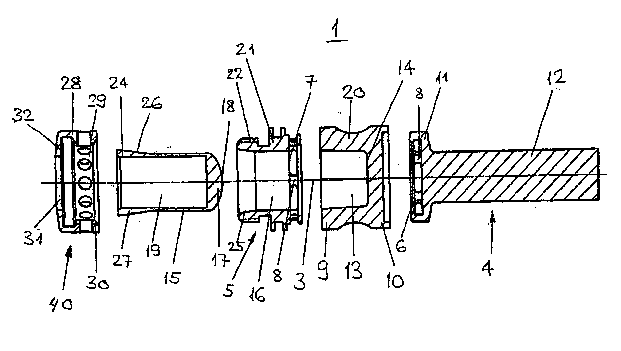
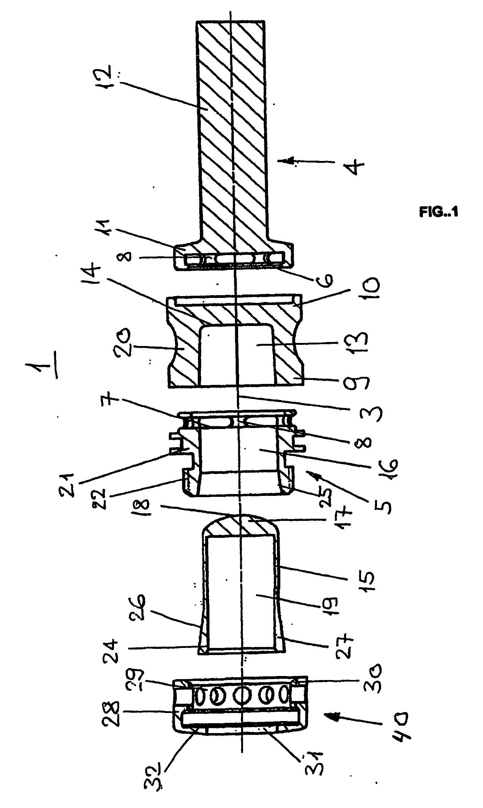
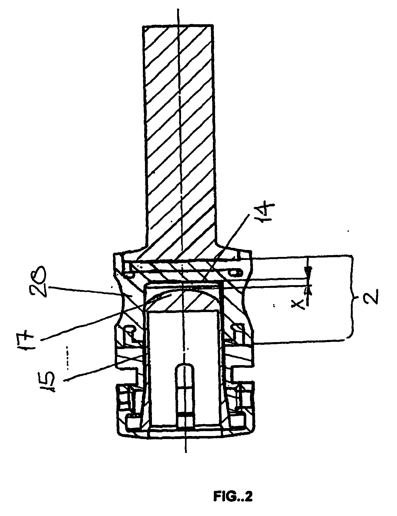
[0019]FIGS. 1 and 2 show an embodiment of a damping element 1 with a longitudinal axis 3, an external longitudinal connecting part 4, an axially opposed external hollow body-shaped connecting part 5 and an elastic means 2 provided coaxially between them.

[0020] The hollow body-shaped connecting part 5 is constructed as a hollow cylindrical bushing 21 and has an outside diameter corresponding to that of the elastic middle part 2. The longitudinal connecting part 4 comprises axially externally a cylindrical rod 12 and a flange 11 bordering the elastic middle part 2, the outside diameter of the flange corresponding approximately to that of the elastic middle part 2. The hollow body-shaped connecting part 5 has a first face 7 which is directed towards the elastic middle part 2 and is perpendicular to the longitudinal axis 3. Similarly to that, the flange 11 has a second face 6 which is directed towards the elastic middle part 2 and is perpendicular to the longitudinal axis 3.

[0021] The...


PUM


Abstract

A damping element for the dynamic stabilization of two bones, particularly of two adjacent bodies of the vertebra, includes a flexible spring element having a hollow space. The hollow space is open on a first end and closed on a second end by a wall extending transversely to the longitudinal axis of the damping element. A clamping sleeve is inserted at least partially into the hollow space. The sleeve has a front end directed towards the wall of the flexible spring element. The distance between the front end and the wall affects the damping characteristics of the damping element. A coaxial connecting element is attached to each end of the flexible spring element. Each connecting element is configured to be connected within an osteosynthetic stabilizing device.

Description

CROSS REFERENCE TO RELATED APPLICATION [0001] This is a continuation of International Patent Application No. PCT / CH2003 / 00649, filed Sep. 29, 2003, the entire contents of which are incorporated herein by reference thereto.TECHNICAL FIELD OF THE INVENTION [0002] The invention is directed to a damping element having a generally cylindrical flexible element with dynamically changing damping characteristics. BACKGROUND OF THE INVENTION [0003] Damping elements that can be used, for example, as a connecting element between two adjacent pedicle screws within a fixing device for the spinal column are known. Such known damping elements comprise essentially two axially external longitudinal connecting elements and a part provided between them, that is made from a material having a greater elastic deformability than the external connecting elements. A disadvantage of this known damping element is that the spring characteristics of the middle, elastic part is determined by the geometry and the ...

Claims


Application Information

Patent Timeline
Patent Type & Authority Applications(United States)
IPC IPC(8): A61F2/30A61B17/56A61B17/70
CPCA61B17/7004Y10T403/455A61B17/7031A61B17/7025
Inventor HARTMANN, STEPHAN
Owner SYNTHES USA
Why Eureka
Try Eureka