Encapsulated beam with anti-rotation system

a technology of anti-rotation and encapsulation beam, which is applied in the direction of carpet cleaners, cleaning machines, vehicles, etc., can solve the problems of inability to provide equal, little force, if any, and lack of uniform wiping force applied to the wiper blade, so as to increase the downward force of the wiper assembly and prevent any twisting

Inactive Publication Date: 2006-11-30
TENNECO AUTOMOTIVE OPERATING CO INC
View PDF99 Cites 52 Cited by
  • Summary
  • Abstract
  • Description
  • Claims
  • Application Information

AI Technical Summary

Benefits of technology

[0011] A further object of the present invention is to provide a wiper blade having an encapsulated beam which prevents the rotation and twisting of the resilient wiper blade around the support beam.
[0012] It is another object of the present invention to provide a wiper blade having an encapsulated beam further comprising a wind deflector portion to further assist in preventing the twisting of the resilient wiping blade around the beam.
[0014] Another object of the present invention is to provide a wiper beam having a construction whereas the beam can be isolated from the windshield wiper connector system, while still preventing the rotation of the resilient portion relative to the beam.
[0015] Finally, it is an object of the present invention to provide a wiper blade having an encapsulated beam further comprising a fluid passage along the encapsulated beam member for allowing washing / de-icing fluid to be dispersed along the length of the wiper blade.
[0016] These and other objects will become more apparent, wherein the present invention encompasses an improved windshield wiper blade assembly, having a resilient windscreen wiping element and further comprising a longitudinal passage there through. A support beam having a predetermined curvature and shape complementary to the longitudinal passage is inserted there within the passage in a manner which prevents the rotational twisting of the resilient element around the beam. A further embodiment comprises a longitudinal fluid passage along the support beam, having a fluid connection to a windshield fluid supply. A plurality of apertures through the resilient member in connection with the fluid passage provide for the selective discharge of the fluid upon the windscreen. A still further embodiment comprises a symmetrical wind deflector portion running at least partially along the top side of the resilient member for enhanced prevention of any twisting of the resilient member around the beam, and increased downward force of the wiper assembly against the windscreen.

Problems solved by technology

This problem is often at least partly due to the failure of the wiper assembly to apply a uniform wiping force against the length of the wiper blade and thus also to the surface of the windshield.
The lack of uniformity in the wiping force applied to the wiper blade is characterized by conventional wiper assemblies having superstructures which apply a force load upon the wiper blade at only relatively widely spaced intervals.
As a result little, if any, force may be available at various locations between these spaced intervals.
Just as the great variety of windshield wiper designs share a certain commonality of structure, they also share certain disadvantages in carrying out the basic task at hand.
This arrangement is believed to be inherently unable to provide equal force distribution when the radius of curvature varies along the length of the blade, not to mention the joint between the backing member and the wiper blade is exposed to the elements.
A common problem of this design is the twisting of the resilient portion around the support beam due to frictional forces imposed upon the wiping blade during its oscillations.

Method used


Image

  • Encapsulated beam with anti-rotation system
  • Encapsulated beam with anti-rotation system
  • Encapsulated beam with anti-rotation system

Examples


Embodiment Construction

[0089] The following description of the preferred embodiments is merely exemplary in nature and is in no way intended to limit the invention, its application, or uses.

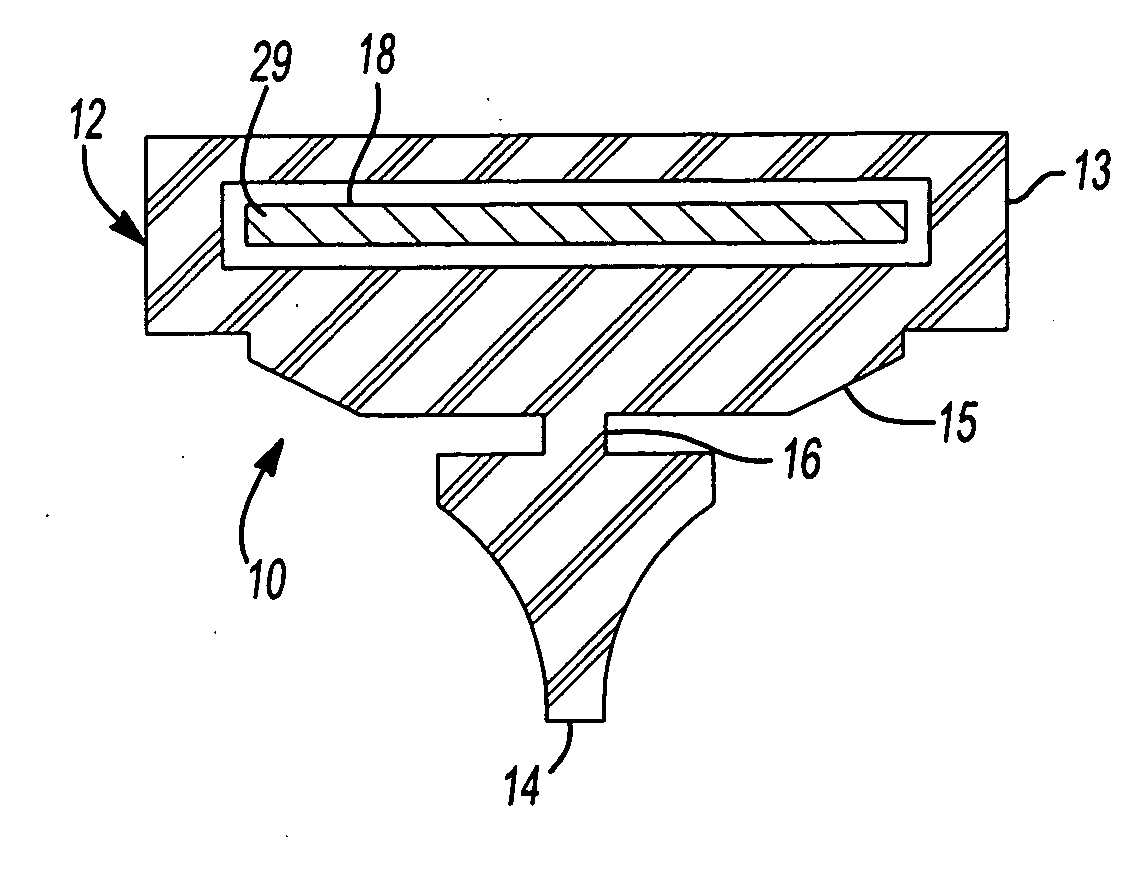
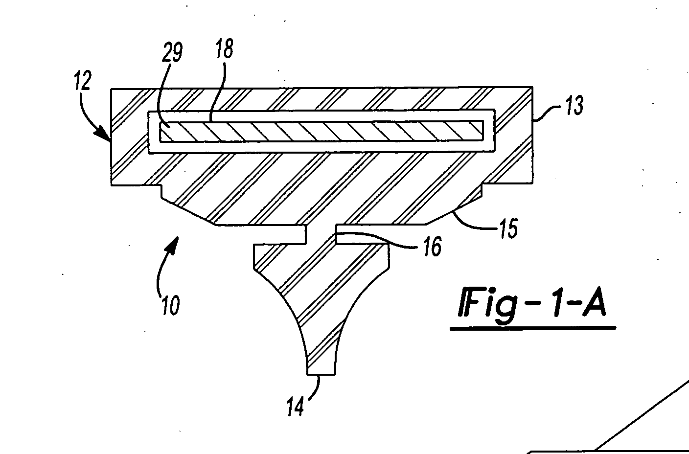
[0090] Referring now to the figures, particularly FIGS. A-1 and A-2, a first embodiment of the encapsulated beam assembly 10 of the present invention is shown comprising elongated resilient member 12 having a body 13 and a windscreen wiping edge 14 pivotally attached to a bottom side 15 thereof by a narrow flexible neck 16. The body 13 further comprises a longitudinal passage 18 through which an elongated beam 19 of a predetermined stiffness is inserted, thereby becoming encapsulated by the resilient member 12. The shape of the passage 18 is generally complementary to the shape of the elongated beam 19, thereby preventing the rotational twisting of the resilient member 12 independently of the elongated beam 19.

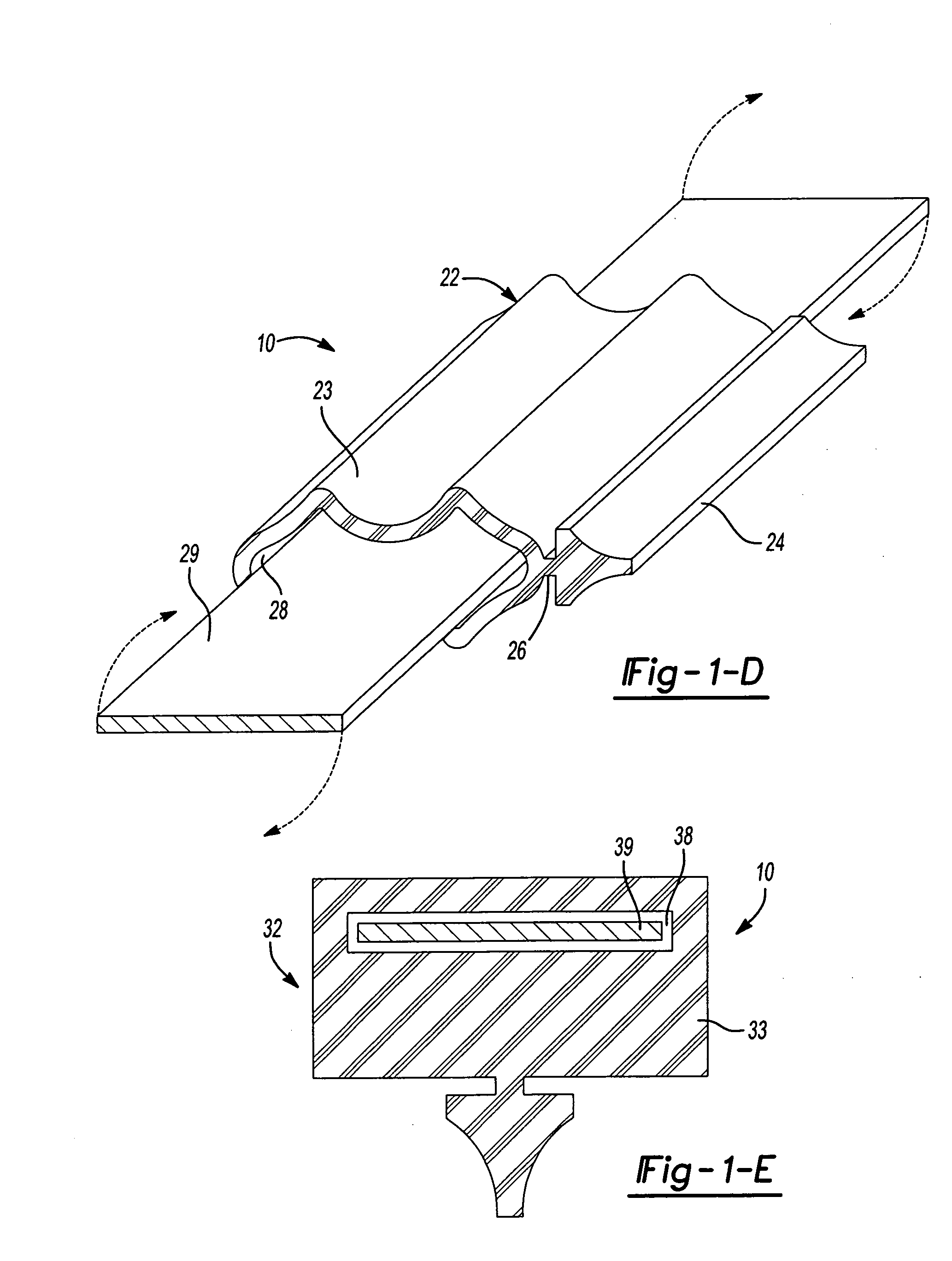
[0091] FIGS. A-3 and A-4 illustrate an alternative embodiment of the encapsulated beam assembly 10 of the pr...


PUM


Abstract

An improved windshield wiper blade assembly having a resilient windscreen wiping element and further comprising a longitudinal passage there through. A support beam having a predetermined curvature and shape is positioned there within the passage having a generally complementary cross section to the longitudinal passage, preventing the rotational twisting of the resilient element around the beam. A further embodiment comprises a longitudinal fluid passage along the support beam in fluid connection to a windshield fluid supply. A plurality of apertures through the resilient member in connection with the fluid passage provide for the selective discharge of the fluid upon the windscreen. A still further embodiment comprises a wind deflector portion running at least partially along the resilient member for enhanced prevention of any twisting of the resilient member around the beam and increased downward force of the wiper assembly against the windscreen.

Description

CROSS-REFERENCE TO RELATED APPLICATIONS [0001] This application claims the benefit of U.S. Provisional Application No. 60 / 652,807, filed on Feb. 14, 2005. The disclosure of the above application is incorporated herein by reference.FIELD OF THE INVENTION [0002] The present invention relates to windshield wiping blade assemblies. More particularly this invention relates to resilient windshield wiping blades having an encapsulated support beam element. BACKGROUND OF THE INVENTION [0003] A frequently encountered shortcoming in the design of conventional automotive windshield wipers is observed when the surface which has been wiped on the windshield is left with bands or streaks. This problem is often at least partly due to the failure of the wiper assembly to apply a uniform wiping force against the length of the wiper blade and thus also to the surface of the windshield. The lack of uniformity in the wiping force applied to the wiper blade is characterized by conventional wiper assembl...

Claims


Application Information

Patent Timeline
Patent Type & Authority Applications(United States)
IPC IPC(8): A47L13/02
CPCB60S1/38B60S1/3808B60S1/381B60S1/3856B60S1/524B60S1/3877B60S2001/3817B60S2001/382B60S2001/3836B60S1/3862B60S1/4006B60S1/46B60S1/40
Inventor WALWORTH, VAN T.BOYLE, MARKBACARELLA, JOSEPH C.HOOK, DAVIDMCGINN, WILLIAMMOSER, GEORGE
Owner TENNECO AUTOMOTIVE OPERATING CO INC
Why Eureka
Try Eureka