Centrifugal-effect vibration generator having coaxial contrarotating rotors

a technology of centrifugal force and generator, which is applied in the direction of mechanical vibration separation, mechanical control devices, instruments, etc., can solve the problems of generator weight and bulk, poor efficiency, and high electricity consumption

Active Publication Date: 2006-11-30
EUROCOPTER +1
View PDF4 Cites 26 Cited by
  • Summary
  • Abstract
  • Description
  • Claims
  • Application Information

AI Technical Summary

Benefits of technology

[0014] An object of the invention is to propose a force generator that is controllable in amplitude, in frequency, and preferably in direction, that is improved and / or that remedies, at least in part, the drawbacks of vibration generators (or “suppressors”) for aircraft.

Problems solved by technology

i) poor efficiency which leads to high consumption of electricity, and also requires a powerful amplifier to be used on the control signal;
It is also known to use a rotary actuator comprising unbalanced rotors (having unbalance weights) for producing forces by the centrifugal effect.
Such a generator is also heavy and bulky.

Method used


Image

  • Centrifugal-effect vibration generator having coaxial contrarotating rotors
  • Centrifugal-effect vibration generator having coaxial contrarotating rotors
  • Centrifugal-effect vibration generator having coaxial contrarotating rotors

Examples


third embodiment

[0048] In the third embodiment corresponding to FIGS. 3 and 5, the direction 50 of the alternating force generated by the device is stationary: it is colinear with the axis 51 tracing the plane 39 that is perpendicular to the axes of rotation 17, this axis 51 intersecting both axes of rotation 17.

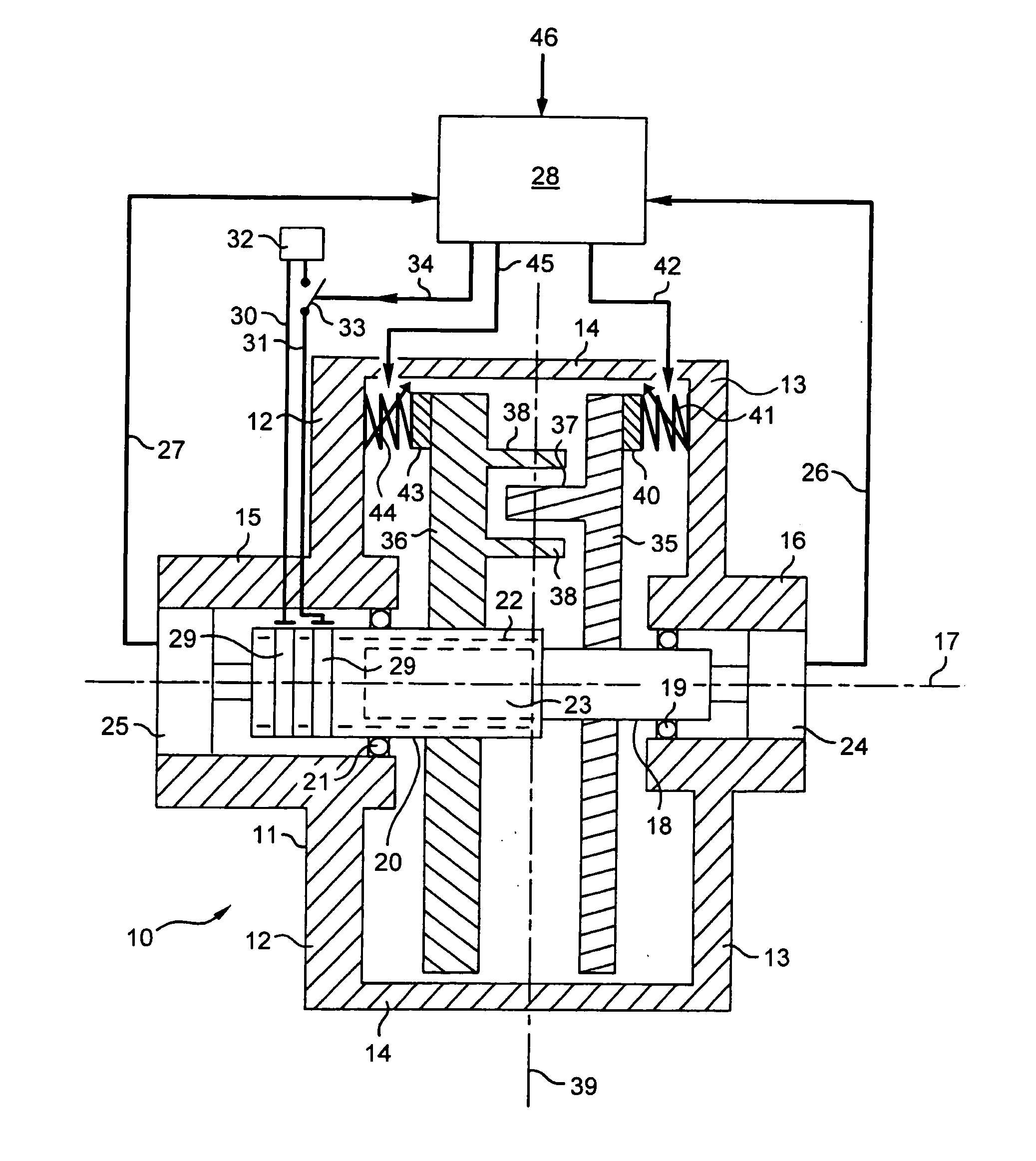
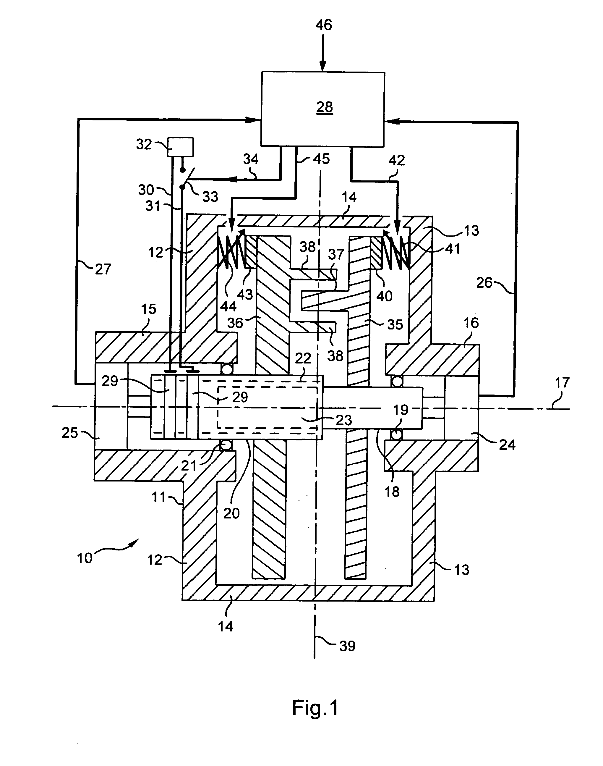
[0049] In this embodiment, the device has two assemblies identical to that shown in FIG. 1, with axes of rotation 17 that are parallel and spaced apart by a distance 52; the two pairs of contrarotating and coaxial unbalanced rotors are mounted in a common casing 11 to 14.

[0050] In the first two embodiments (FIGS. 1, 2, and 4), the direction of the overall force generated by the unbalanced rotors is controlled by the contrarotating movement of each pair of flyweights. This corresponds to controlling the slip speed between the rotor 18 and the rotary “stator”20 of each pair of rotors in the drive system, so as to ensure that the flyweights 37 and 38 rotate in opposite directions. This contro...

second embodiment

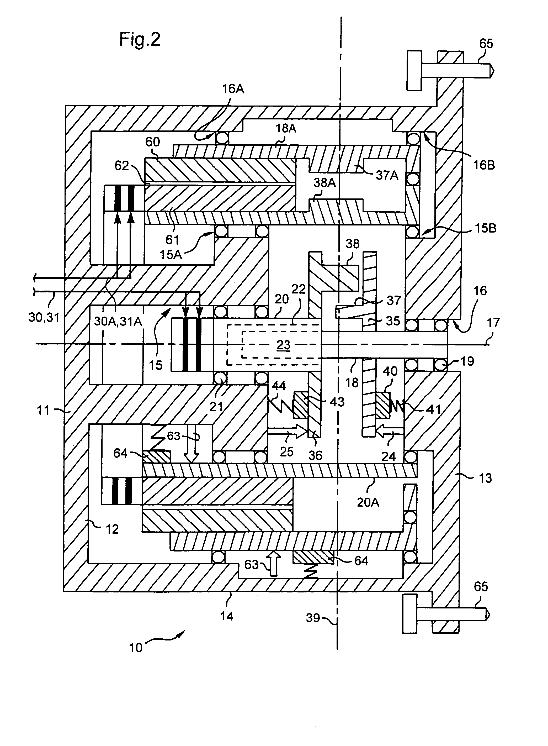
[0053] In FIGS. 2 and 4, the device has a second pair of contrarotating rotors on the axis of rotation 17 of the first pair of rotors: a “driven” third rotor 18A and a “driving” fourth rotor 20A are mounted in the casing via respective bearings 16A, 16B and 15A, 15B.

[0054] The rotors 18A, 20A are in the form of cylinders or drums about the axis 17; the rotor 18A includes a magnetic circuit 60 while the rotor 20A carries an electromagnetic circuit 61 facing the circuit 60 and separated therefrom by an airgap 62; the circuit 61 is connected to a power supply (not shown) via slip rings and conductors 30A, 31A.

[0055] These rotors are fitted with respective unbalance weights 37A, 38A; a rotation sensor 63 and a brake 64 are associated with each of the rotors 18A, 20A and are used as described above to control the speed and the phase of each of the rotors at all times.

[0056] With reference to FIGS. 2 and 4, screws 65 are provided for securing the apparatus 10 to a support (not shown) th...


PUM


Abstract

A device for generating forces that are variable and controllable in amplitude, in direction, and in frequency, the device includes two unbalanced rotors (18, 20, 35 to 38) mounted coaxially in a casing (11). The device further includes electromagnetic drive elements for driving a first of the two rotors in rotation relative to the second of the two rotors, and brake elements (43 to 45) for braking the second rotor (20, 36, 38) relative to the casing.

Description

[0001] The present invention relates to a centrifugal-effect vibration generator comprising a plurality of coaxial and contrarotating rotors. [0002] The technical field of the invention is that of actively attenuating vibration on board helicopters and other rotary wing aircraft. BACKGROUND OF THE INVENTION [0003] It is known to fit such aircraft with actuators for eliminating or attenuating the aircraft vibration that results in particular from the alternating forces applied to the fuselage by the mechanism that provides the aircraft with lift and propulsion. [0004] To this end, aircraft vibration is measured using at least one accelerometer delivering a vibration measurement signal, the measurement signal is processed by processor means including an algorithm recorded in an electronic card or in an on-board computer, so as to obtain a control signal that is applied to an actuator in order to generate forces that oppose the measured vibration. [0005] The forces may result from the ...

Claims


Application Information

Patent Timeline
Patent Type & Authority Applications(United States)
IPC IPC(8): E02D7/18F16F9/12F16F15/22
CPCB06B1/166B64C27/001B64C2027/005Y10T74/18344Y10T74/2112Y10T74/18552F16F15/22
Inventor CLARY, SYLVAIN
Owner EUROCOPTER
Why Eureka
Try Eureka