Optical sight with side focus adjustment

a technology of optical sight and side focus, which is applied in the direction of mountings, instruments, weapons, etc., can solve the problems of reducing sticking and jumping, etc., and achieves reliable windage and elevation adjustment, reduce the optical performance of the scope, and strengthen the weight and bulk.

Inactive Publication Date: 2007-03-22
BUSHNELL
View PDF7 Cites 10 Cited by
  • Summary
  • Abstract
  • Description
  • Claims
  • Application Information

AI Technical Summary

Benefits of technology

[0014] A variety of scope designs with different features are described below. For example, various embodiments of the invention comprise a side-mounted focus adjustment assembly. In one embodiment, the side focus assembly includes a rotatable knob arranged generally to the side of the central tube portion of the scope. This rotatable knob may, in particular embodiments, be arranged generally at the same axially location along the center tube portion as elevation and / or windage adjustment assemblies. The focus assembly may be radially displaced from these other adjustment assemblies. The side-mounted focus assembly includes a mechanism such that by rotating the knob, a focus lens assembly internal to the scope is induced to move axially within the scope so as to adjust the focus of an image viewed by a user of the scope as seen from the ocular or eyepiece end. The side-mount focus assembly can be advantageously utilized with a unitary main scope tube which is materially continuous from the objective or distal end to the ocular or proximal end and thus does not include the threaded joints of many known scopes. Thus, the side mount focus assembly can provide a desirably focus adjustment to a scope having a unitary main tube and thus with the strength, weight, and bulk advantages desired by users of the scope. In different embodiments, the side focus can also optionally be used with a flexible erector that may optionally be biased and springless to provide reliable windage and elevation adjustments.
[0015] The diameters of the central tube holding optical components may have a generally standardized at diameters of either one (1) inch or thirty (30) millimeters. The focus may be accomplished with a rotating knob which moves an internally arranged focus lens assembly axially along the main axis of the scope to provide the desired focus adjustment. To convert the rotation motion to axial motion of a lens does not need multiple large profile moving components or layers inside the central body that occupy additional space inside the central body and interfere with the scopes normal operation and reduce optical performance of the scope.

Problems solved by technology

In contrast, many conventional system rely on forward spring designs with ball seats that have machined grooves that cause sticking and jumping when adjusting the windage or elevation.
To convert the rotation motion to axial motion of a lens does not need multiple large profile moving components or layers inside the central body that occupy additional space inside the central body and interfere with the scopes normal operation and reduce optical performance of the scope.

Method used


Image

  • Optical sight with side focus adjustment
  • Optical sight with side focus adjustment
  • Optical sight with side focus adjustment

Examples


Embodiment Construction

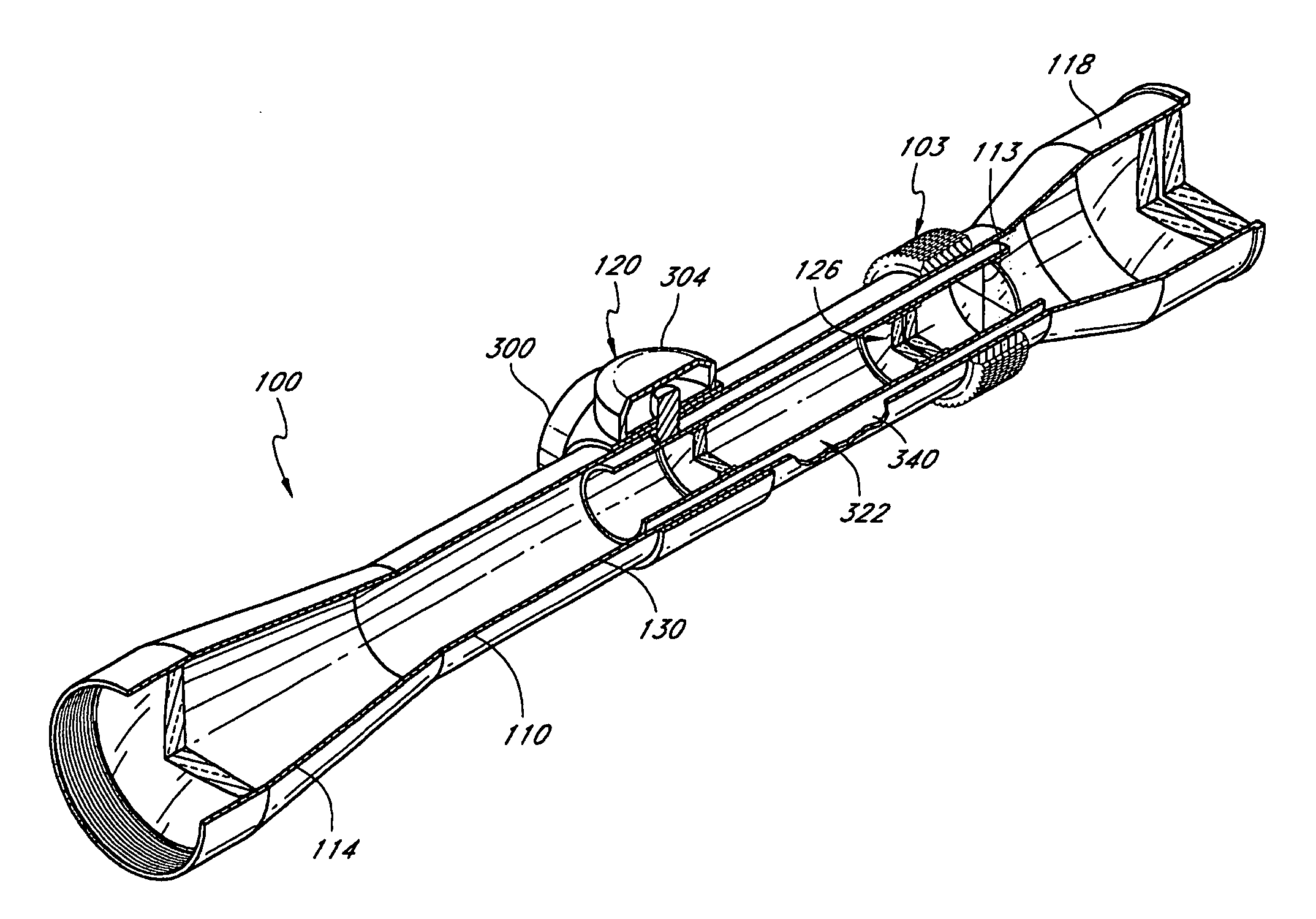
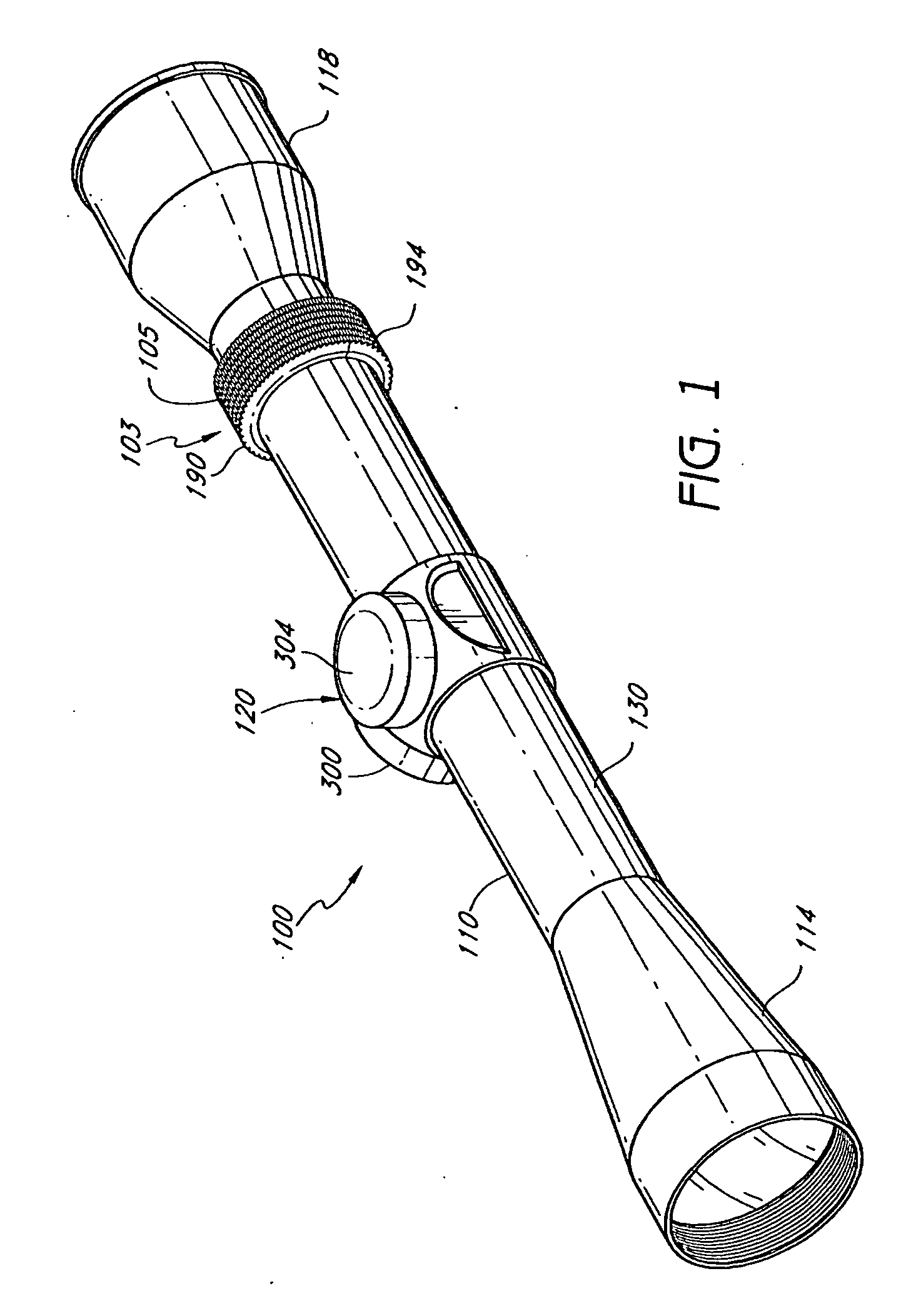
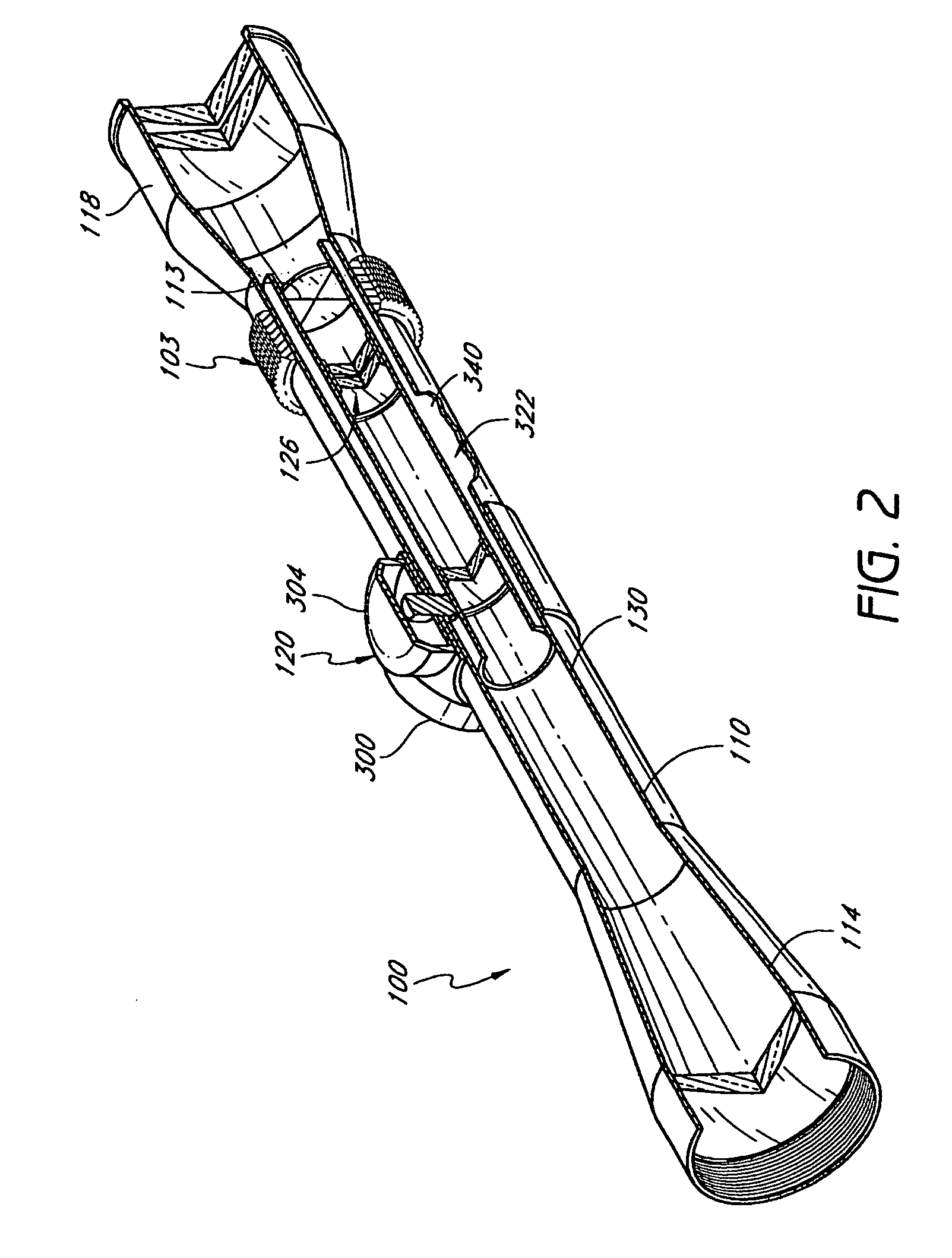
[0050] These and other aspects, advantages, and features of the present teachings will become apparent from the following detailed description and with reference to the accompanying drawings. In the drawings, similar elements have similar reference numerals. To assist the description of the scope and its components, the following coordinate terms are used. The terms proximal and distal, which are used to describe the disclosed embodiments, are used consistently with the description of the exemplary applications. The terms proximal and distal are used in reference to the head of the user looking through the scope. That is, proximal components are nearer to the user than distal components.

[0051]FIG. 1 illustrates a scope 100 that has a zoom assembly 103 for providing selectable zoom thereby controlling the apparent distance to an object viewed through the scope. The zoom assembly 103 includes the zoom selector ring 105 that is disposed along and surrounds a main body 110 of the scope...


PUM


Abstract

A scope for a firearm can be used for a gun sight. The scope comprises a main tube that contains imaging optics therein. In certain embodiments, the main tube comprises a single continuous tubular body extending uninterrupted from a widened proximal end portion through a narrow medial portion to a widened distal end portion. A side focus assembly is positioned along the tubular body. The side focus assembly is used to vary the position of optics within the scope to adjust the overall focus of the scope.

Description

RELATED APPLICATIONS [0001] This application is a continuation of U.S. patent application Ser. No. 11 / 271,487 entitled “Optical Sight with Side Focus Adjustment” filed Nov. 10, 2005, which is a continuation-in-part of U.S. application Ser. No. 10 / 994,491, entitled “Scope With Improved Windage / Elevation System” filed Nov. 22, 2004 and which also claims priority to U.S. Provisional Patent Application No. 60 / 647,201 entitled “Optical Sight with Side Focus Adjustment” filed on Jan. 26, 2005 (MIC.052PR) as well as to U.S. Provisional Patent Application No. 60 / 647,686 entitled “Adjustable Optical Sighting Apparatus and Methods” filed on Jan. 27, 2005 (MIC.055PR). The entire disclosure of the above-noted patent applications are hereby incorporated by reference herein and made a part of this specification.BACKGROUND [0002] 1. Field of the Invention [0003] The present teachings relate to a scope for mounting on a firearm to provide a gun sight. Such a scope may have a side focus capability. ...

Claims


Application Information

Patent Timeline
Patent Type & Authority Applications(United States)
IPC IPC(8): F41G1/38
CPCF41G1/38G02B7/023G02B7/022
Inventor THOMAS, MARK A.THOMAS, MITCHELLBABCOCK, FORREST
Owner BUSHNELL
Why Eureka
Try Eureka