Method and apparatus for dissipating heat

a technology of apparatus and heat dissipation device, which is applied in the direction of cooling/ventilation/heating modification, semiconductor/solid-state device details, semiconductor devices, etc., can solve the problem of increasing heat generation of components, and achieve the effect of limited heat load and difficult fabrication

Inactive Publication Date: 2006-11-30
SENSIS CORPORATION
View PDF14 Cites 23 Cited by
  • Summary
  • Abstract
  • Description
  • Claims
  • Application Information

AI Technical Summary

Benefits of technology

[0009] The present invention provides thermally enhanced packages for high heat density electronic components which allow for extracting heat from extremely localized areas, effectively spreading this heat over a larger area, thereby decreasing its density, and efficiently transferring the heat to the equipment's cooling media. The package preferably incorporates a unique combination of high thermal conductivity and thermal-expansion matched materials. The high thermal conductivity of the materials (when provided) promotes heat conduction away from the components. The matched thermal expansion of the materials, to that of the components (when provided), minimizes the occurrences of the stresses in the components with temperature excursions.
[0020] A thermally enhanced package design according to the present invention preferably employs all solid-type materials, i.e., no internal fluids. There is no fundamental factor which limits either the heat loads or temperature ranges at which it functions. Preferably, the package design is compact and self-contained. The package design lends itself to production of electronic assemblies by being producible, and consequently affordable, using developed manufacturing processes. By contrast, alternative approaches for thermally enhancing electronic packaging have typically limited heat load and temperature ranges, are typically bulky and complex, and / or difficult to fabricate, rendering them costly.
[0021] The thermally enhanced packages according to the present invention enable insertion of new electronic component technologies into commercial and military systems with application to computers, transportation, communications, sensors, opto-electronics, and industrial controls. With this component packaging, systems using air-based cooling can be extended to higher power levels, deferring the need to transition to liquid coolant. For the highest power systems, the thermally enhanced packaging may also be advantageously employed with a liquid coolant media.

Problems solved by technology

As a consequence, these components are generating increasingly larger amounts of heat in smaller areas.
Removal of this heat has been identified as perhaps the biggest issue facing computer designers.

Method used


Image

  • Method and apparatus for dissipating heat
  • Method and apparatus for dissipating heat
  • Method and apparatus for dissipating heat

Examples


Embodiment Construction

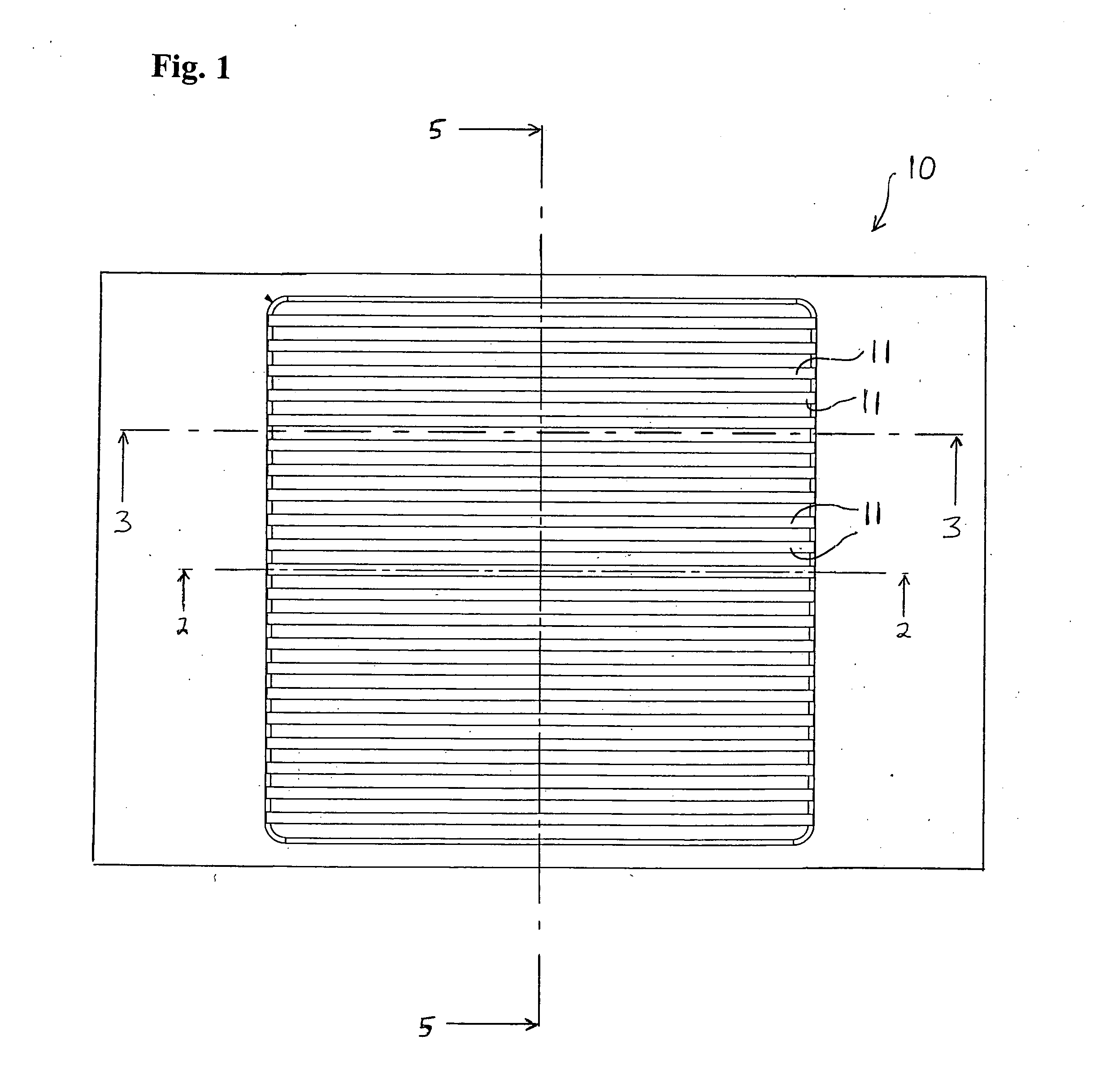
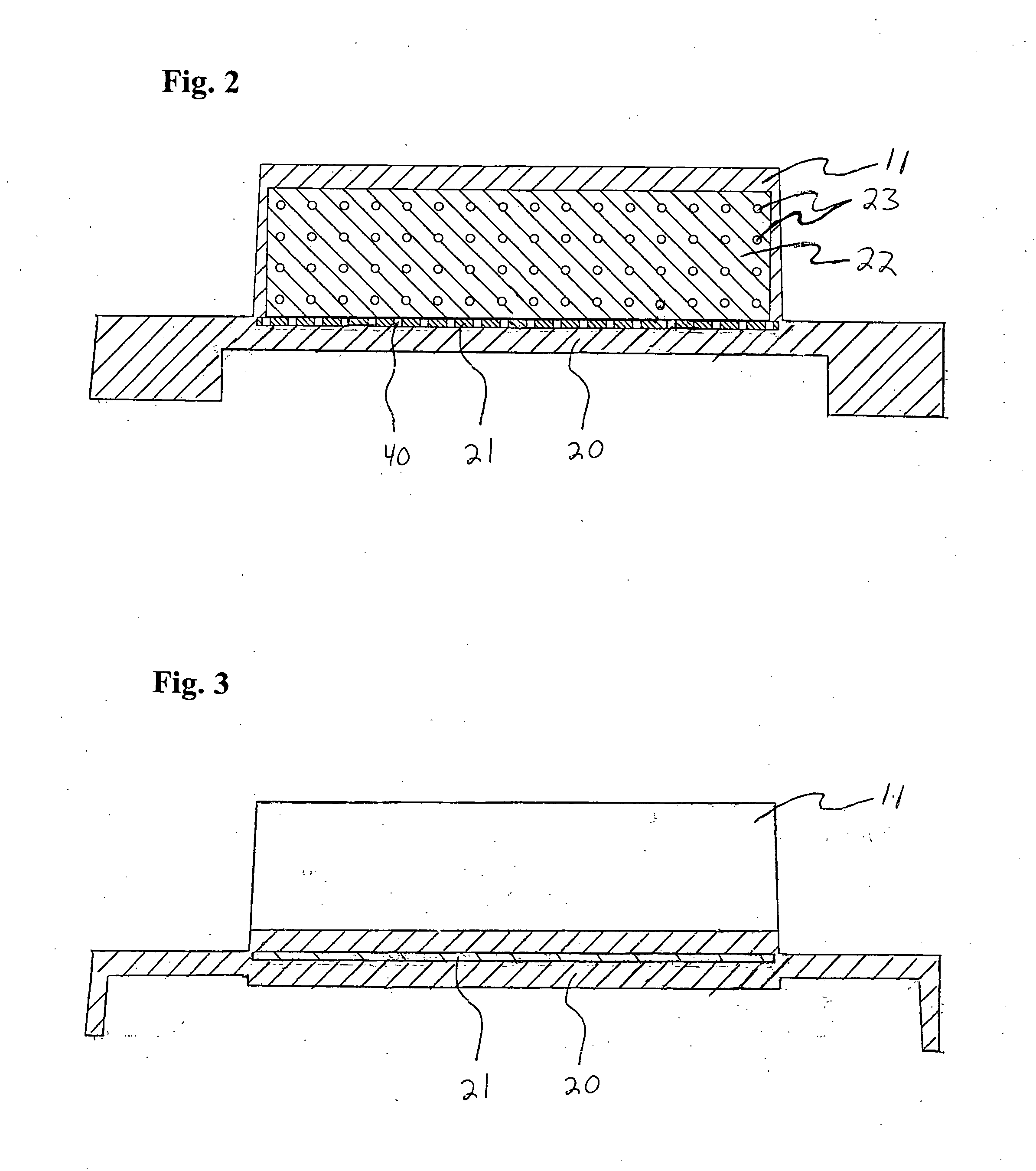
[0033] As noted above, in accordance with the present invention, there is provided a heat dissipation device comprising a base, a base element, protrusions and protrusion elements.

[0034] The base can comprise any suitable material. Preferably, the base comprises a material which readily transfers heat. In one aspect, the base can comprise a metal matrix composite, i.e., a material made by infusing (e.g., by melting and injecting) a metal into a porous pre-form. For example, a representative example of a preferred base is a base which comprises AlSiC, preferably in the form of a metal matrix composite. In a preferred aspect of the present invention, the base consists of and / or consists essentially of AlSiC, preferably in the form of a metal matrix composite.

[0035] As noted above, the base element is positioned within the base.

[0036] The base element can be formed from any suitable material, preferably a material which has an extremely high heat transfer coefficient. For example, a...


PUM


Abstract

There is provided a heat dissipation device comprising a base, a base element positioned within the base, protrusions extending from the base, and protrusion elements positioned within the protrusions. Also provided are methods of dissipating heat, comprising passing fluid across and / or through such devices.

Description

FIELD OF THE INVENTION [0001] The present invention relates to apparatus for dissipating heat. The present invention further relates to the thermal management of electronic components, and more particularly, limiting temperatures of components generating heat at very high density. The present invention further relates to methods of dissipating heat, e.g., from electronic components. [0002] In preferred aspects, the present invention relates to apparatus for dissipating heat from electronic components, e.g., electronic components for a radar antenna. BACKGROUND OF THE INVENTION [0003] Evolving electronic components are operating at higher speeds and higher power levels and are being packed more and more densely. As a consequence, these components are generating increasingly larger amounts of heat in smaller areas. To limit the temperatures of these components, and thereby realize peak performance plus reliable operation, this heat energy must be effectively removed. [0004] The contin...

Claims


Application Information

Patent Timeline
Patent Type & Authority Applications(United States)
IPC IPC(8): H05K7/20
CPCH01L23/3677H01L23/373H01L23/3731H01L23/3732H01L23/3736H01L2924/0002H01L2924/3011H01L2924/00
Inventor EDWARD, BRIAN J.RUZICKA, PETER J.
Owner SENSIS CORPORATION
Why Eureka
Try Eureka