Multifluid heat exchanger

Active Publication Date: 2006-11-30
DANA CANADA CORP
View PDF34 Cites 52 Cited by
  • Summary
  • Abstract
  • Description
  • Claims
  • Application Information

AI Technical Summary

Benefits of technology

[0008] In the present invention, three or more fluid passages or conduits are provided where heat energy can be transferred efficiently between any one of the fluid conduits and each of the other fluid conduits.

Problems solved by technology

As may be appreciated, this usually involves a lot of plumbing, and in automotive applications, it is highly undesirable to have too many components that need to be assembled into the automobile, as that increases the cost of assembly, provides more components that can break down, and it takes up valuable space, which is always in short supply.
While all of the above-mentioned prior art devices achieve the desired result of compact design and simplification of the plumbing, they are all concerned with transferring heat between one common fluid and two other fluids.
They are not concerned with transferring heat energy between the two other fluids per se, and consequently, they are not very efficient at doing that.

Method used


Image

  • Multifluid heat exchanger
  • Multifluid heat exchanger
  • Multifluid heat exchanger

Examples


Embodiment Construction

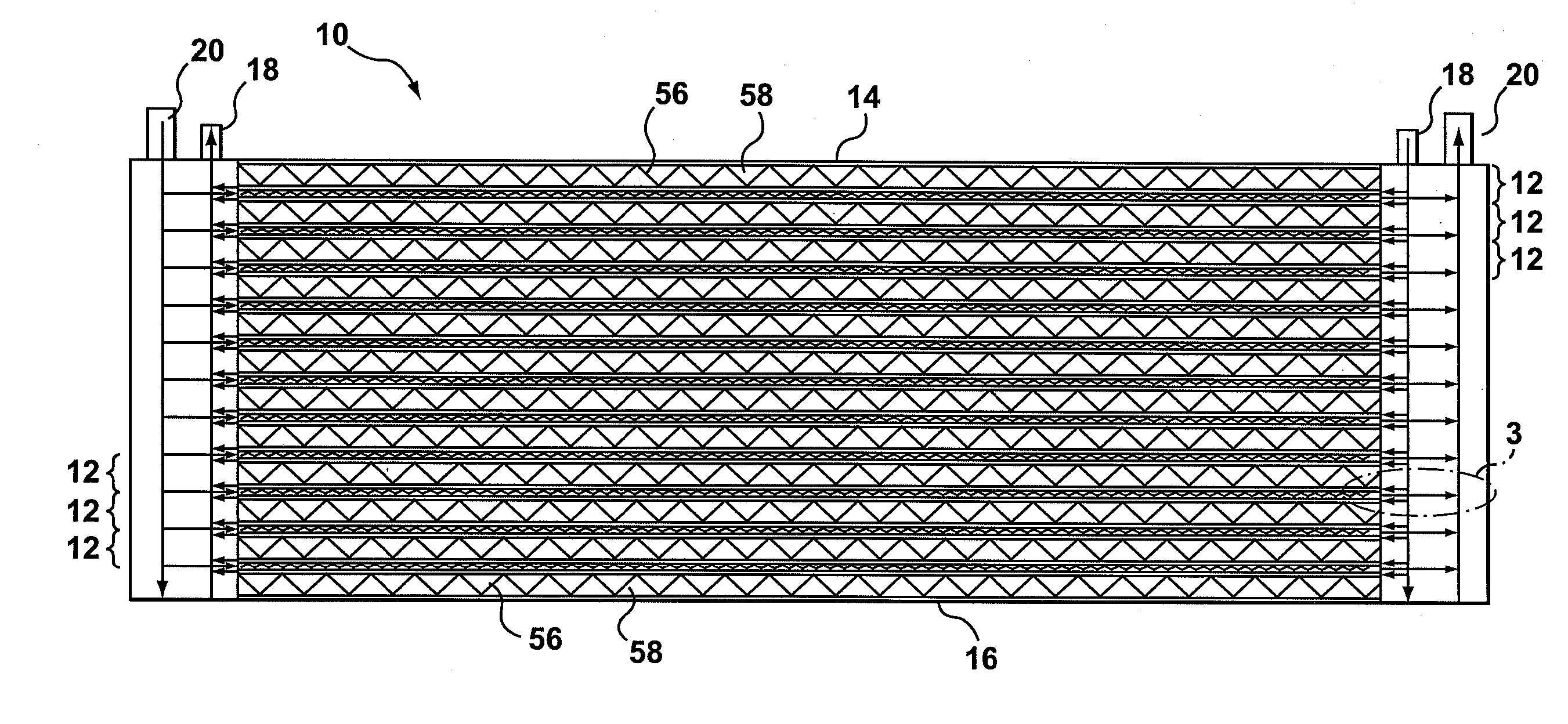
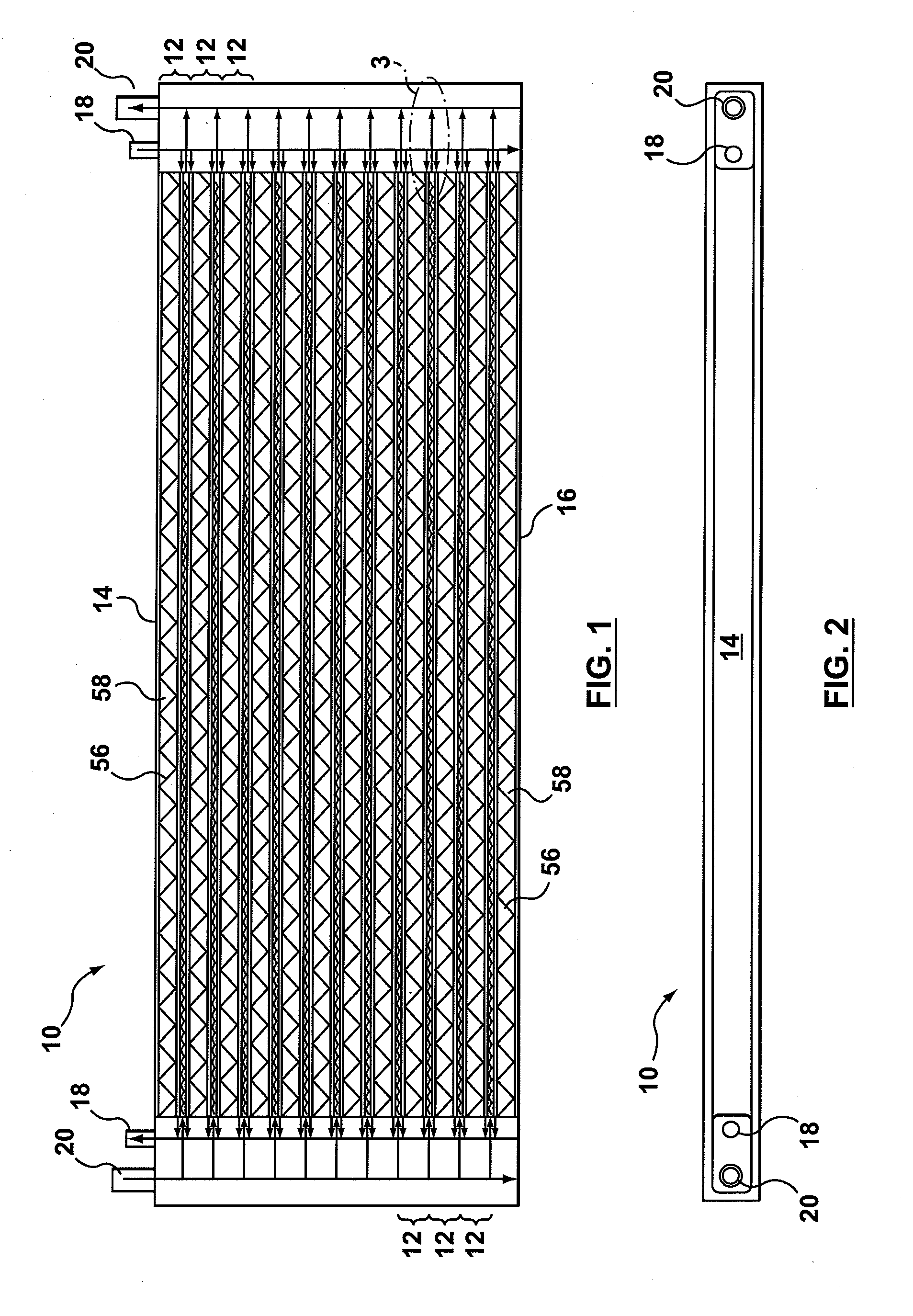
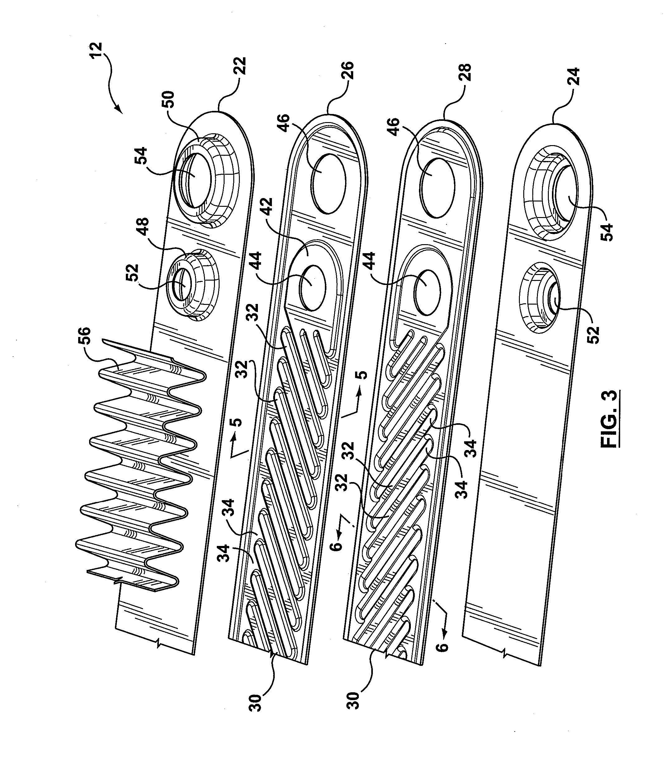
[0025] Referring first to FIGS. 1-7, a first preferred embodiment of a heat exchanger according to the present invention is generally indicated by reference numeral 10. Heat exchanger 10 is formed of a plurality of stacked heat exchange modules 12, the right hand end of one of which is shown best in FIG. 4. Heat exchanger 10 also has a top plate 14 and a bottom plate 16, a pair of inner nipples 18 and a pair of outer nipples 20. The inner and outer nipples 18, 20 form the inlets and outlets for two of the heat exchange fluids used in heat exchanger 10, as will be described further below.

[0026] Each heat exchange module 12 is formed by a pair of spaced-apart plates 22,24 and a pair of back-to-back intermediate plates 26,28. The spaced-apart plates 22,24 are identical, one of them just being turned upside down. Similarly, intermediate plates 26, 28 are identical, one of them again just being turned upside down. Intermediate plates 26,28 are formed with undulations 30 in the form of p...


PUM


Abstract

A heat exchanger has a pair of heat exchange conduits having adjacent primary heat exchange surfaces thermally coupled together for the transfer of heat energy between the conduits. A third fluid conduit has a primary heat transfer surface thermally coupled to the primary heat transfer surfaces of the pair of fluid conduits, so that heat can be transferred between any one of the fluid conduits and each of the other fluid conduits.

Description

RELATED APPLICATIONS [0001] This application claims priority from U.S. provisional patent application Ser. No. 60 / 684,037 filed May 24, 2005, which is incorporated herein by reference.FIELD OF THE INVENTION [0002] This invention relates to heat exchangers, and in particular, to heat exchangers for transferring heat energy between more than two fluids. BACKGROUND OF THE INVENTION [0003] In some applications, such as automotive vehicle manufacturing, it is common to have multiple heat exchangers for cooling or heating various different fluids that are used in the application. For example, in the case of an automobile, it is common to have a radiator for cooling the engine coolant, and one or more other heat exchangers for cooling such fluids as engine oil, transmission oil or fluid, power steering fluid, etc. Usually, air is used to cool the engine coolant, and often the engine coolant itself is used to cool the other fluids, such as engine or transmission oil or power steering fluid....

Claims


Application Information

Patent Timeline
IPC IPC(8): F28D7/16
CPCF28D1/0246F28D1/0333F28F2009/0287F28D1/05383F28F2210/04F28D1/0461F28D9/005F28D1/02F28F3/08F28D9/00
Inventor SO, ALLAN K.KOZDRAS, MARK S.
Owner DANA CANADA CORP
Why Eureka
Try Eureka