Sample tube holder

a tube holder and sample technology, applied in the field of sample tube holders, can solve the problems of loss of samples or contamination of analyzers, and achieve the effects of reducing stress, preventing carryover contamination, and reducing siz

Inactive Publication Date: 2006-11-30
GEN PROBE INC
View PDF4 Cites 73 Cited by
  • Summary
  • Abstract
  • Description
  • Claims
  • Application Information

AI Technical Summary

Benefits of technology

[0008] In one embodiment of the present invention, a spacer is included for joining the first sample tube holding structure to the second sample tube holding structure. By providing spatial separation between the finger springs of the first and second sample tube holding structures, the spacer aids in maintaining sample tubes held by the sample tube holder in substantially upright orientations. A particularly preferred spacer of the present invention defines a series of chambers, where each chamber is aligned with and extends between a set of aligned openings in the first and second sample tube holding structures. Each chamber of the spacer is sized to receive a sample tube therein.
[0009] In another embodiment of the present invention, a series of partitions extend upward from the base and divide the base into a plurality of sample tube receiving wells. Each sample tube receiving well is located beneath a chamber of the spacer and a corresponding, aligned set of openings in the first and second sample tube holding structures to collectively form a sample tube compartment. The sample tube compartments function to isolate the sample tubes from each other and help to prevent carryover contamination between the sample tubes. Each sample tube compartment preferably has a slot formed therein to permit viewing of machine readable information (e.g., scannable bar code) affixed to an opposed surface of the chamber and / or to a sample tube which is contained within the sample tube compartment. Machine readable information affixed to a surface of the chamber and visible through the slot can be used to determine whether a sample tube is present in the chamber (i.e., the machine readable information is blocked and cannot be detected by a reader or scanner when the sample tube is present), and machine readable information affixed to a surface of the sample tube and visible through the slot may provide patient identification and / or testing information.
[0010] Each finger spring of the present invention includes an arm portion and an end portion. The arm portions of the finger springs may have, for example, a curved or flat surface in cross-section and are preferably bowed, extending downward and inward from bases about the openings formed in the first and second sample tube holding structures. So that the finger springs bend more uniformly as sample tubes are inserted through sets of finger springs, and to reduce stress at the bases, the arm portions preferably have a hollowed out back side and decrease in size moving in the direction of the end portions from the bases. The end portions of the finger springs preferably have contoured surfaces that provide one or more points of contact with the sample tubes they hold. For example, the end portions of the finger springs may be convexly shaped to permit a single point of contact with the sample tubes or they may be flared, thereby providing continuous contact or multiple points of contact with the sample tubes. Convexly shaped end portions best facilitate the insertion and removal of sample tubes, while end portions having continuous contact or multiple points of contact with the sample tubes may add stability and reduce the number of finger springs needed to maintain the sample tubes in generally upright orientations. To allow for the smooth insertion of flat-bottomed sample tubes, the transition from the arm portion to the end portion of each finger spring is preferably smoothly contoured.
[0012] The openings in the guide structure of the preferred embodiment of the present invention are preferably located so that at least a portion of a closed side wall of a cap joined to each sample tube is contained within a closed wall defining one of the openings when the sample tubes are fully inserted into the sample tube holder (i.e., closed bottom ends of the sample tubes contact the base). Ideally, when a portion of a cap is contained within an opening in the guide structure, the longitudinal axis of the cap deviates from the longitudinal axis of a fluid transfer device (e.g., pipette tip) penetrating the cap by no more than about 0.10 inches (2.54 mm), and the longitudinal axis of the cap deviates from the longitudinal axis of the opening by no more than about 0.020 inches (0.508 mm). The amount of deviation permissible will, of course, depend upon the size of the fluid transfer device and the opening in the cap. Accurately centering the caps prior to piercing them with a robotic pipetting device may limit the force required to penetrate the caps and, accordingly, can provide for more accurate pipetting.

Problems solved by technology

Removal of a sample tube will interrupt the workflow of a laboratory and could result in the loss of a sample or, worse, contamination of an analyzer.

Method used


Image

  • Sample tube holder
  • Sample tube holder
  • Sample tube holder

Examples


Embodiment Construction

[0043] While the present invention may be embodied in a variety of forms, the following description and accompanying drawings are merely intended to disclose some of those forms as specific examples of the present invention. Accordingly, the present invention is not intended to be limited to the forms or embodiments so described and illustrated. Instead, the full scope of the present invention is set forth in the appended claims.

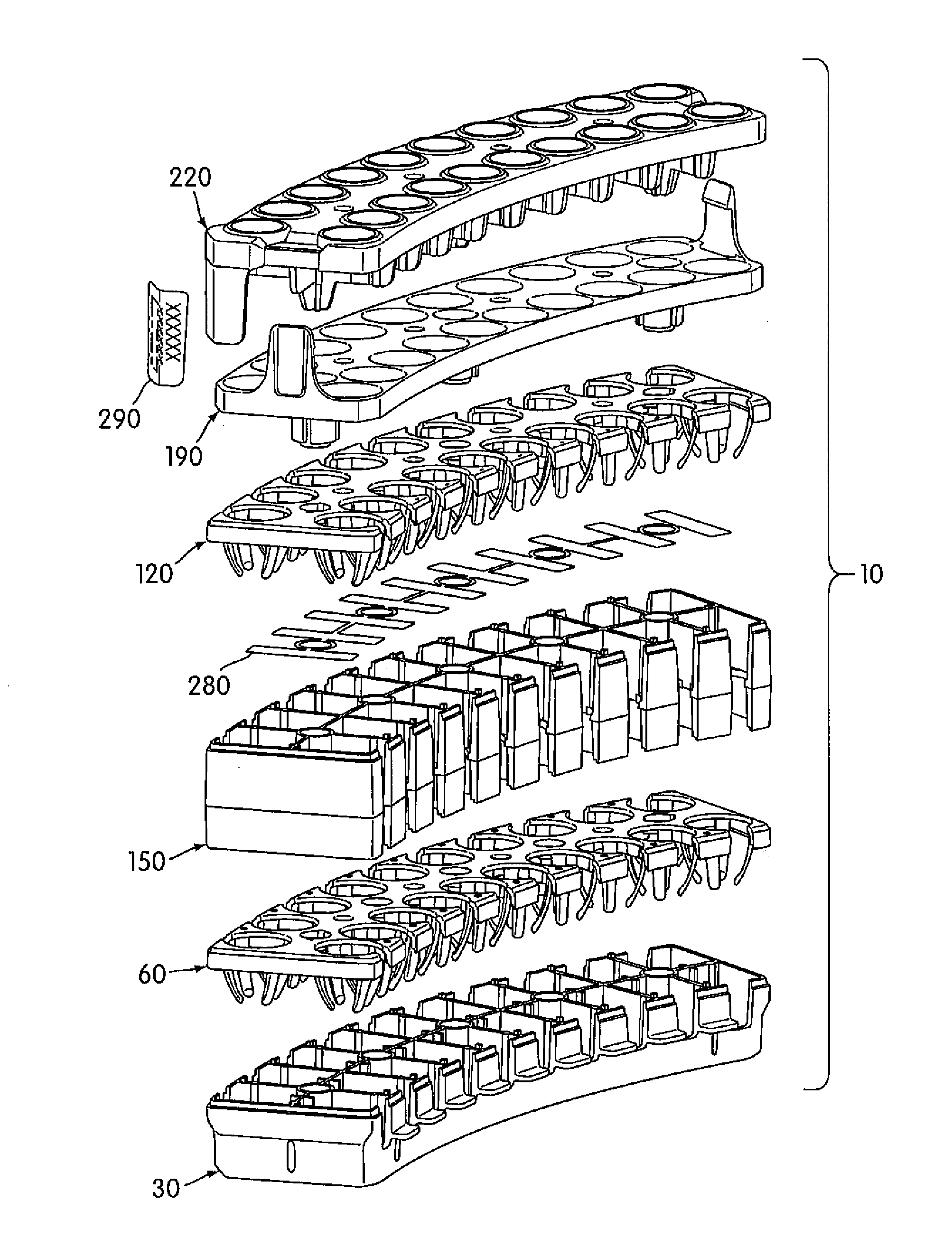
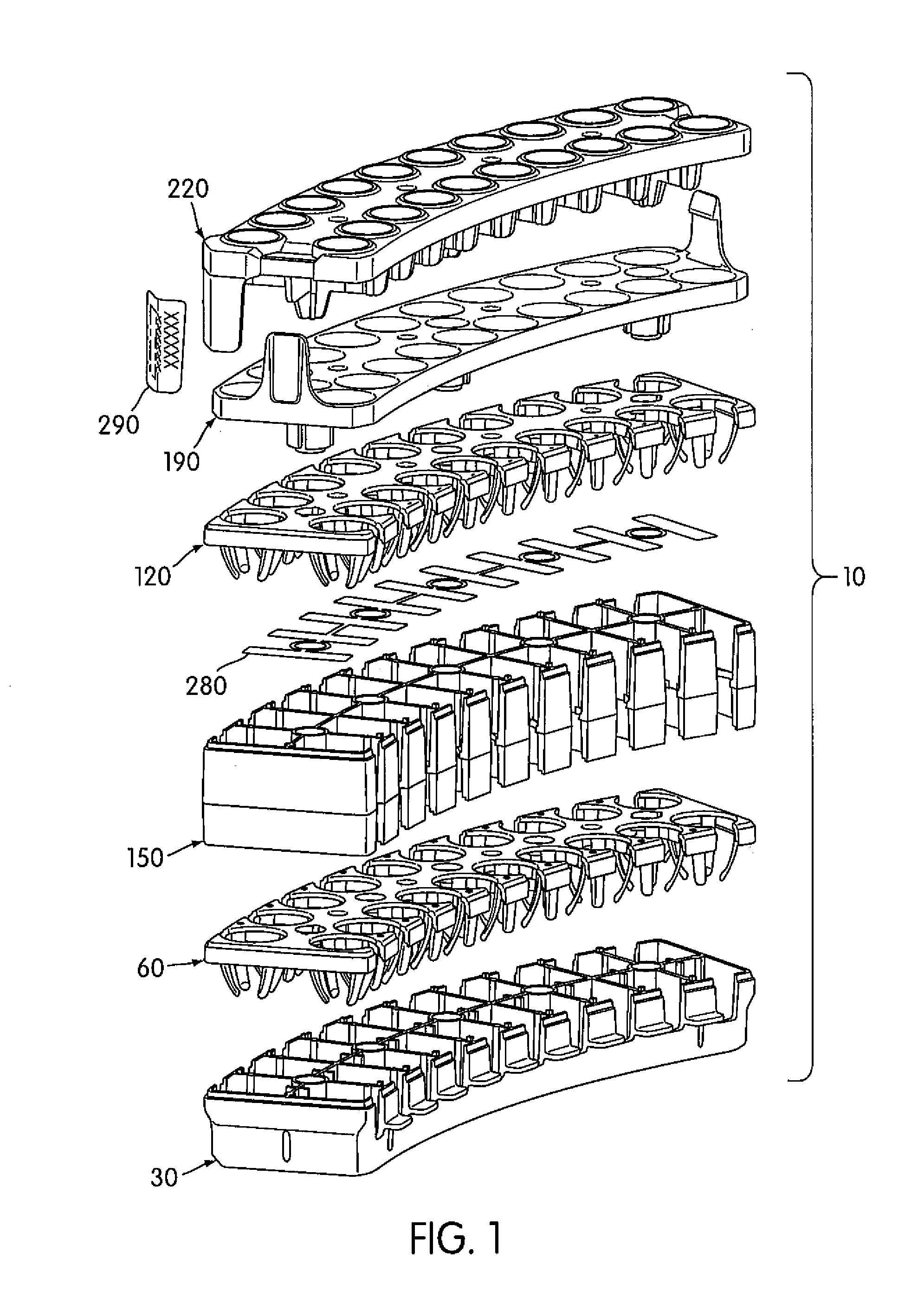
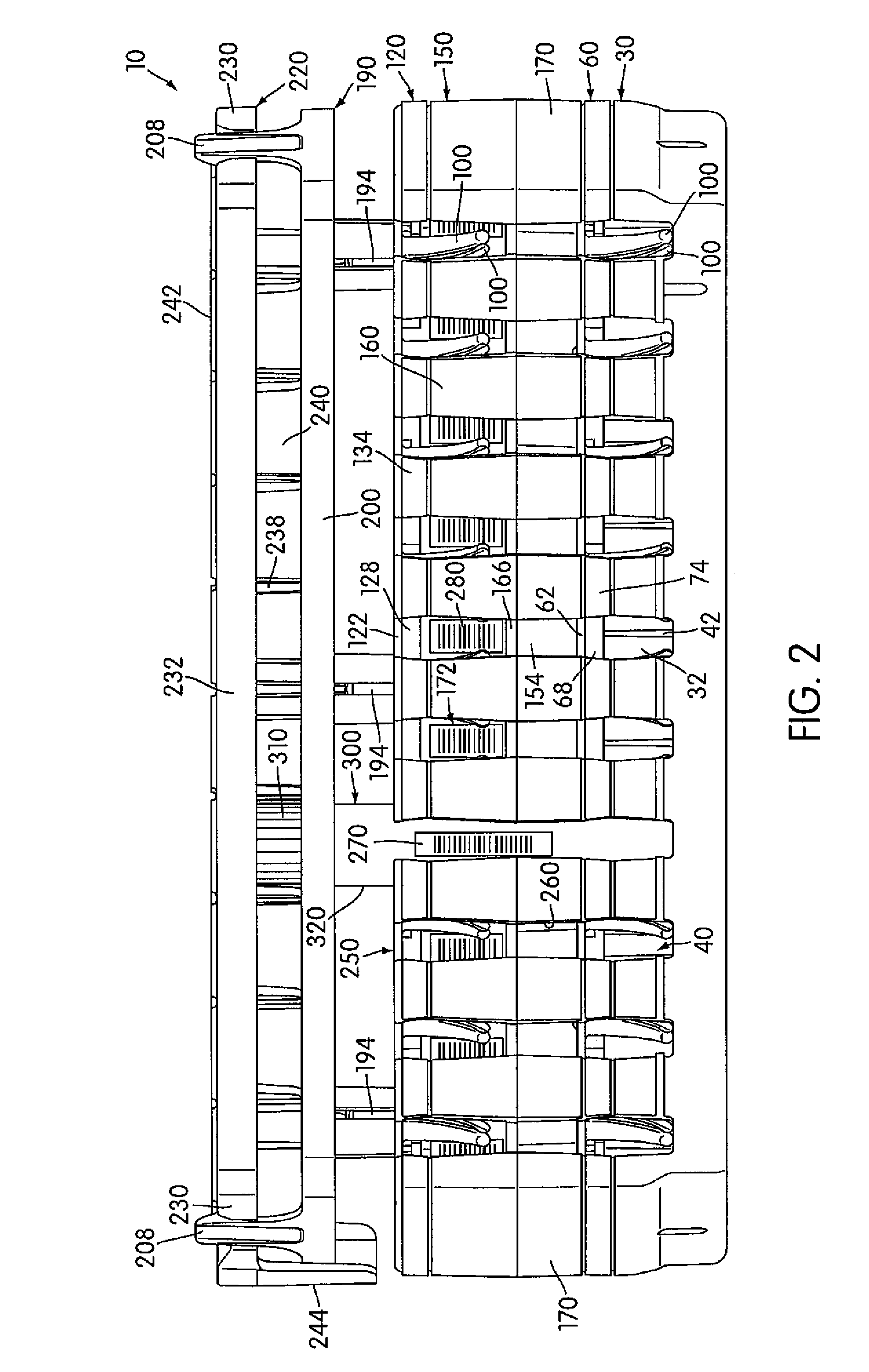
[0044] With reference to the figures, a preferred sample tube holder 10 of the present invention is shown for holding sample tubes 300 and for limiting vertical movement of the sample tube holder when material is being removed from the sample tubes. Sample tube holders 10 of the present invention are preferably used in combination with sample tubes 300 having sealed caps 310 which can be penetrated by plastic pipette tips using an automated pipetting system. A preferred pipetting system for use with the sample tube holders 10 is the Robotic Sample Processor...


PUM


Abstract

A sample tube holder having sample tube compartments with sets of spaced finger springs provided therein for maintaining sample tubes in substantially upright orientations. A guide structure having a series of openings is used to direct sample tubes into the sample tube compartments and to restrict lateral movement of sample tubes held thereby. A retainer is releasably engaged by the guide structure and has openings sized to provide access to sample tubes held by the sample tube compartments but which restrict vertical movement of the sample tubes. Tabs at a base of the sample tube holder and hold-downs fixed to a stationary structure adjacent a conveyor cooperate to restrict vertical movement of the sample tube holder during automated sampling procedures.

Description

CROSS-REFERENCE TO RELATED APPLICATIONS [0001] This application claims the benefit of U.S. Provisional Application No. 60 / 672,609, filed Apr. 19, 2005, the contents of which are hereby incorporated by reference herein.FIELD OF THE INVENTION [0002] The present invention relates to a sample tube holder for holding, aligning and / or retaining a plurality of sample tubes. The sample tube holder of the present invention is especially suited for use with an automated sampling system and sample tubes having penetrable closure devices. BACKGROUND OF THE INVENTION [0003] Automated analyzers are in common use today for assaying the contents of sample tubes for a variety of purposes. Conveyors are often included in these automated analyzers for transporting sample tubes to fluid transfer stations, where robotic pipettors, or other fluid transfer devices, transfer materials to or from the sample tubes. To ensure that materials are being accurately transferred by robotic pipettors, it is importan...

Claims


Application Information

Patent Timeline
Patent Type & Authority Applications(United States)
IPC IPC(8): A47B73/00
CPCB01L9/06B01L2200/025B01L2300/021Y10S435/809G01N2035/0446G01N2035/0451G01N2035/0465G01N35/025
Inventor KNIGHT, BYRON J.TALMER, MARK A.SANDOVAL, ARTHUR G.HOWARD, ROBERT A.HIPOLITO, ROMMEL M.SCALESE, ROBERT F.
Owner GEN PROBE INC
Why Eureka
Try Eureka