

Powder metal cladding nozzle
- Summary
- Abstract
- Description
- Claims
- Application Information
AI Technical Summary
Benefits of technology
Problems solved by technology
Method used
Image

Examples
Embodiment Construction
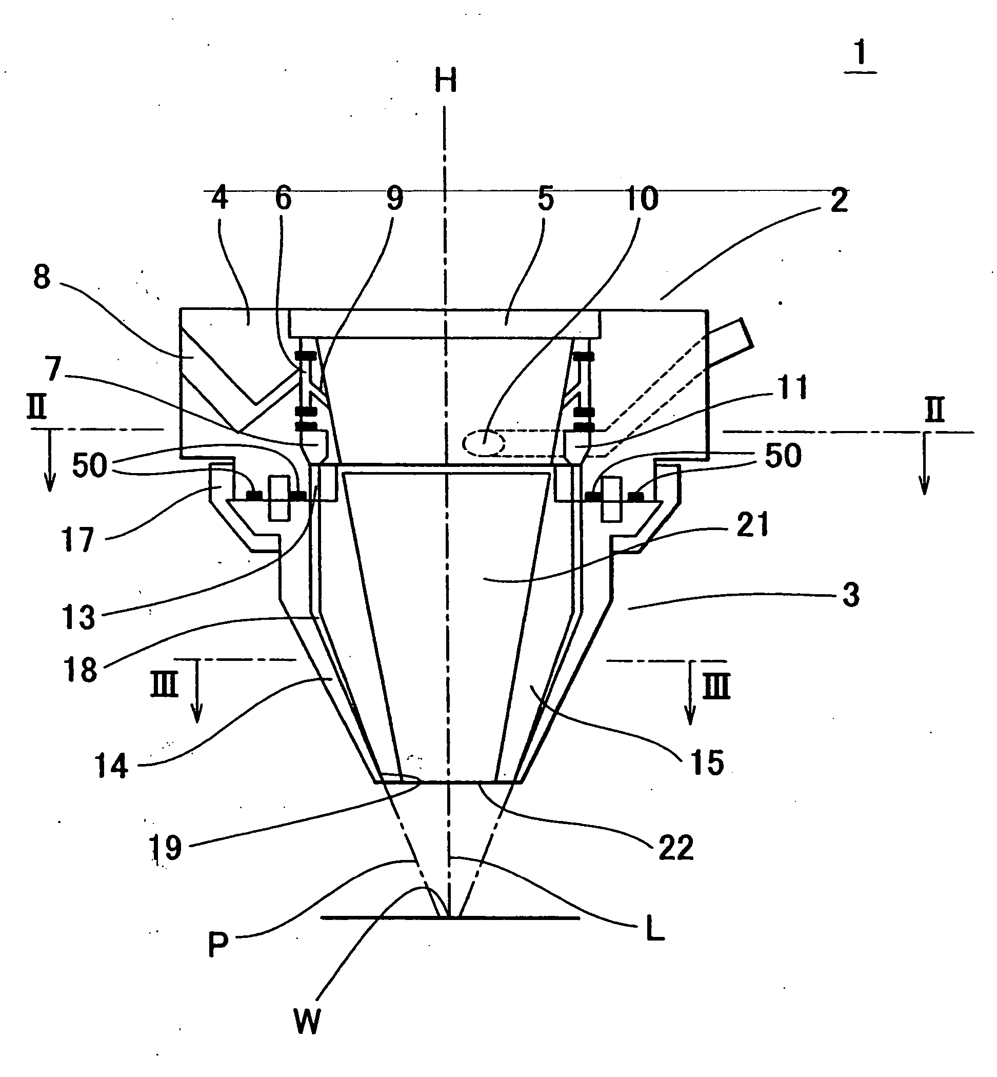
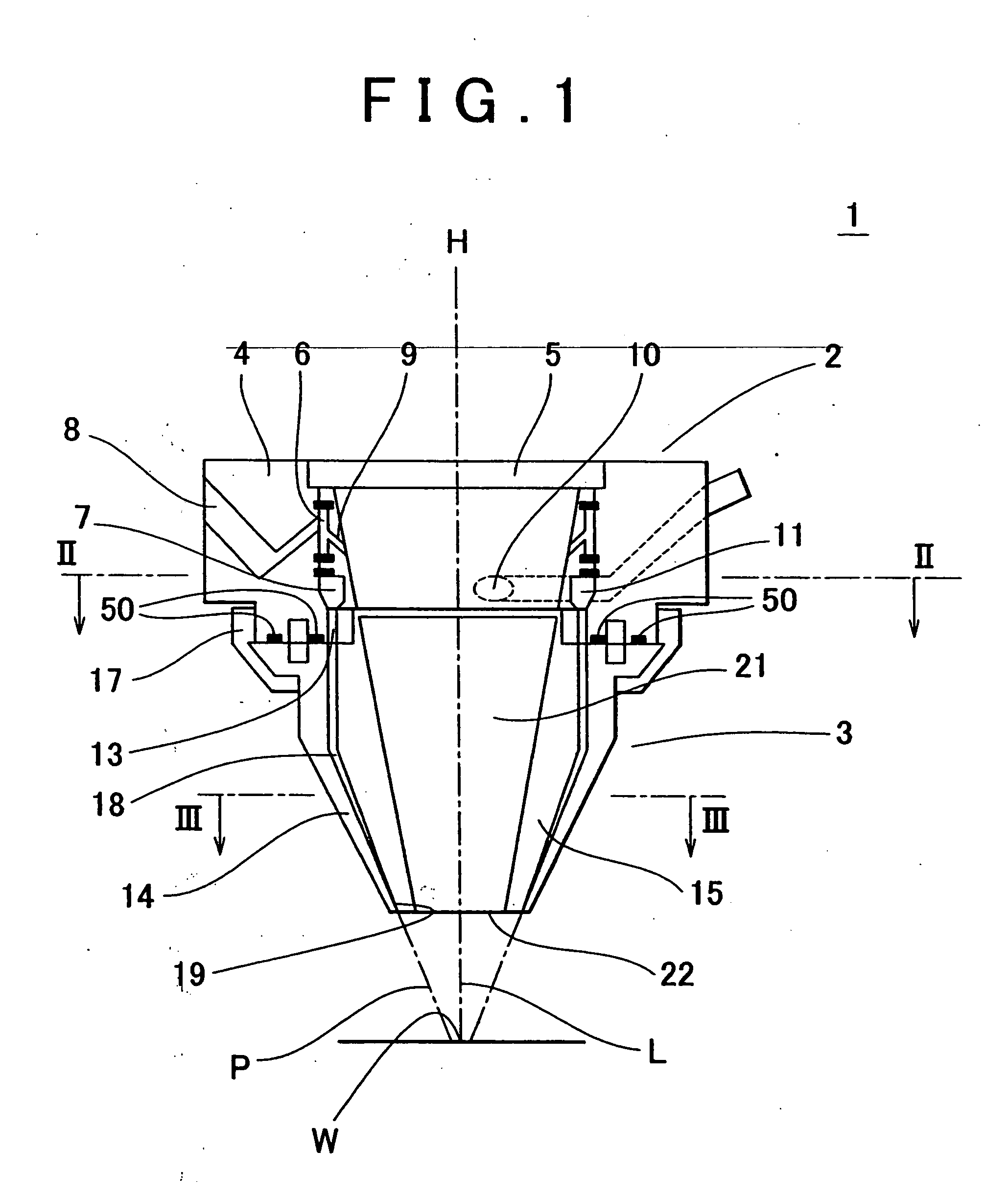
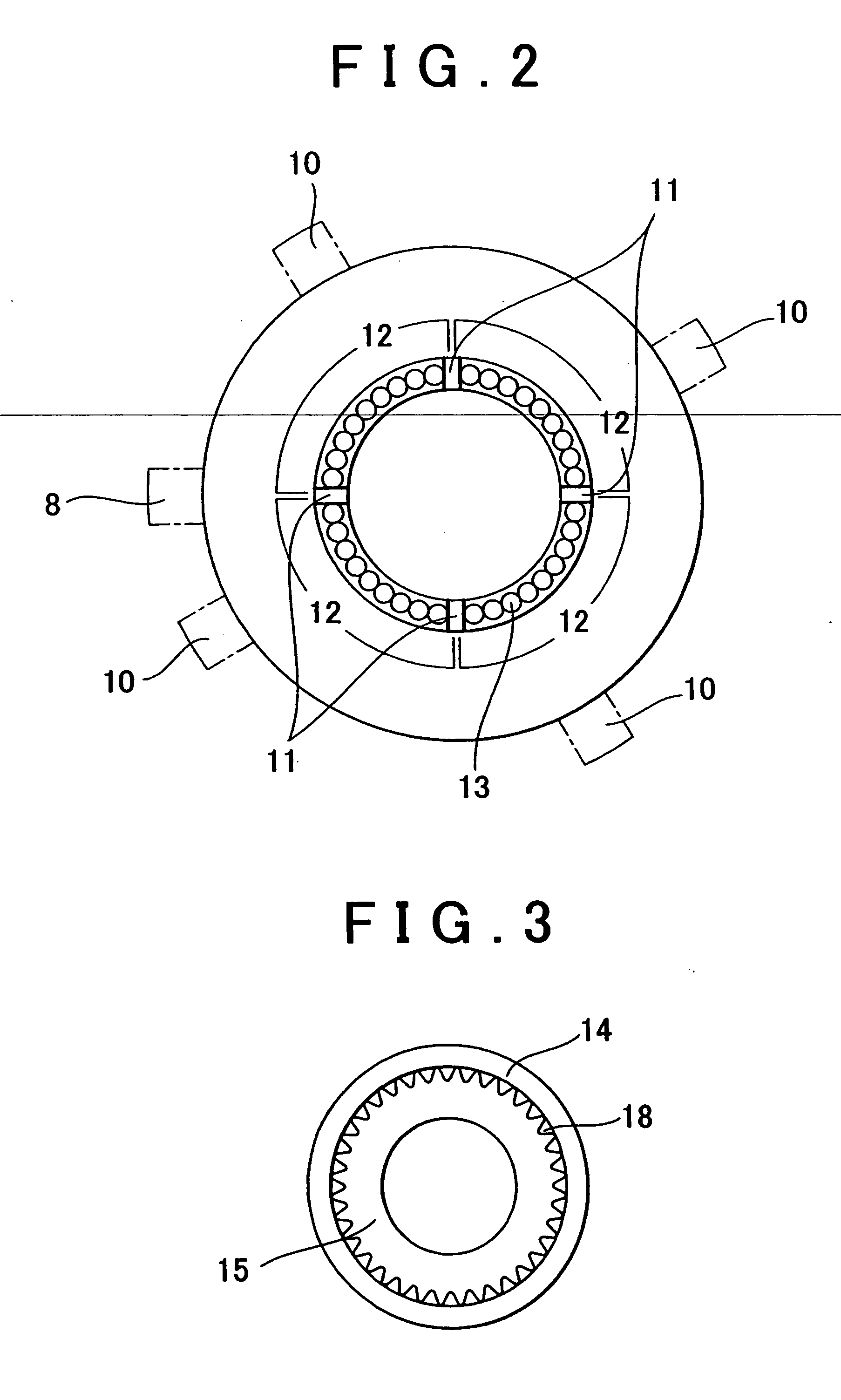
[0039] Hereafter, an embodiment of the invention will be described with reference to FIGS. 1 to 6. FIG. 1 is a cross sectional view schematically showing an entire structure of a powder metal cladding nozzle. FIG. 2 is a cross sectional view taken along line II-II in FIG. 1. FIG. 3 is a cross sectional view taken along line III-III in FIG. 1. Each of FIGS. 4 and 5 shows an inner side member of a nozzle body portion. FIG. 4 is a cross sectional view of the inner side member and FIG. 5 is a front view of the inner side member viewed from the direction of C. FIG. 6 is a side view of an inner side nozzle member of a nozzle portion.
[0040] A powder metal cladding nozzle 1 includes a cylindrical body portion 2, and a nozzle portion 3 which is coaxially coupled to the body portion 2.
[0041] The body portion 2 includes an outer side member 4 and an inner side member 5 which is fitted in a center space of the outer side member 4. A ring-shaped gas holding space 6, in which inert gas is held,...
PUM
| Property | Measurement | Unit |
|---|---|---|
| Distance | aaaaa | aaaaa |
Abstract
Description
Claims
Application Information