Powder metal cladding nozzle

a technology of cladding nozzle and powder metal, which is applied in the direction of coating, laser beam welding apparatus, manufacturing tools, etc., can solve the problems of unbalanced volume of powder metal on the upper side, metal cannot be discharged uniformly, and inability to obtain good cladding layer, etc., to achieve the effect of increasing the powder efficiency of powder metal

Active Publication Date: 2009-12-01
FRAUNHOFER GESELLSCHAFT ZUR FOERDERUNG DER ANGEWANDTEN FORSCHUNG EV +1
View PDF35 Cites 21 Cited by
  • Summary
  • Abstract
  • Description
  • Claims
  • Application Information

AI Technical Summary

Benefits of technology

[0014]By using the groove portions formed in the outer surface of the inner side nozzle member as the powder metal discharge passages, it is possible to easily form and maintain the discharge passages.
[0016]By fitting the inner side nozzle member in the outer side nozzle member such that the end of the inner side nozzle member is retracted with respect to the end of the outer side nozzle member by the predetermined amount in the axial direction of the nozzle portion, the area in the process portion, in which the powder metal is discharged in a concentrated manner, is increased. It is therefore possible to increase powder efficiency of the powder metal.

Problems solved by technology

However, when the nozzle is used while the axis of the nozzle is tilted with respect to the vertical direction, the volume of powder metal on the lower side and the volume of powder metal on the upper side become unbalanced in the passage 107 of the nozzle 100 due to gravity.
Accordingly, the powder metal cannot be discharged uniformly from the opening 104, which causes a problem that a good cladding layer cannot be obtained.

Method used


Image

  • Powder metal cladding nozzle
  • Powder metal cladding nozzle
  • Powder metal cladding nozzle

Examples


Embodiment Construction

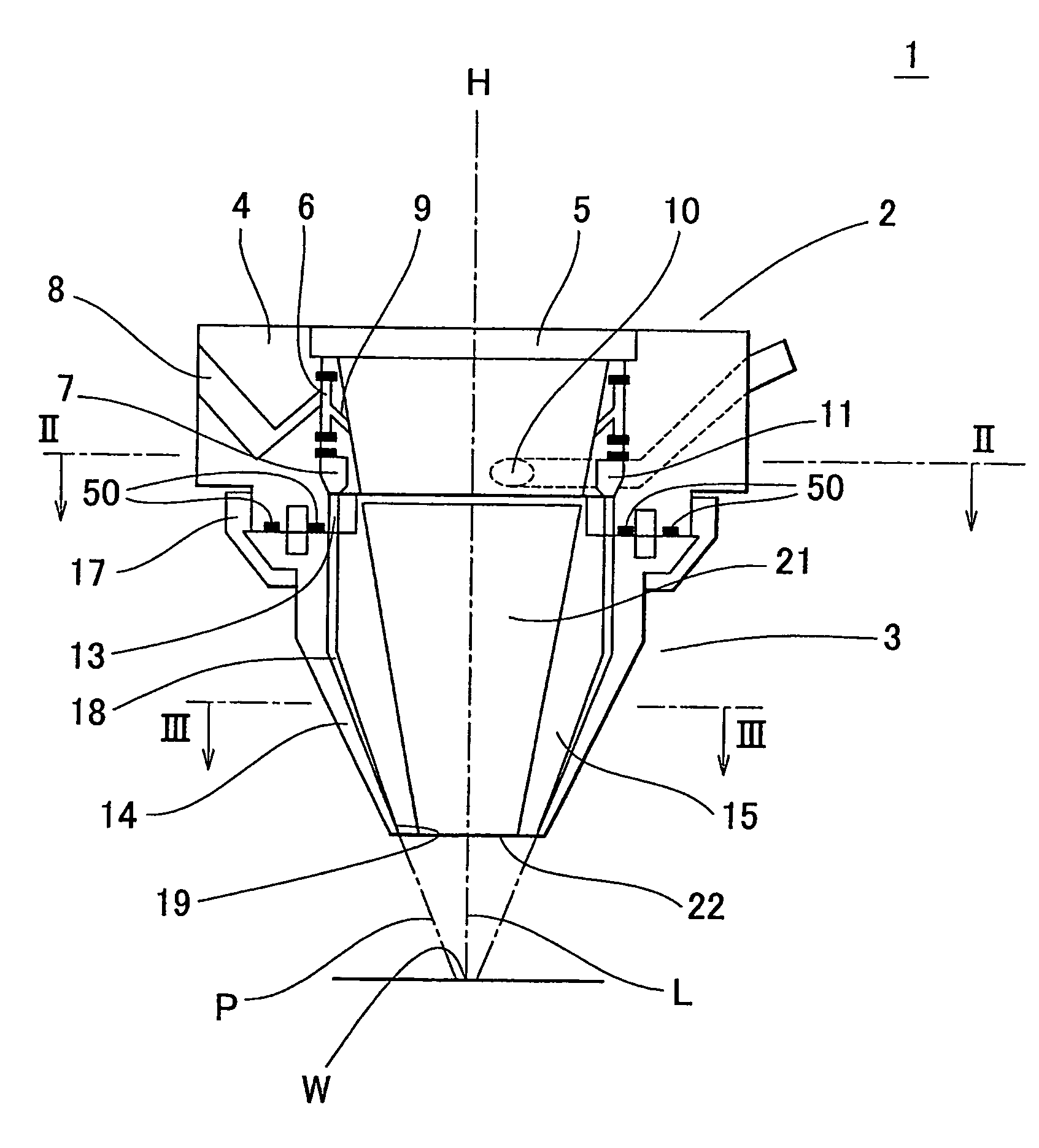
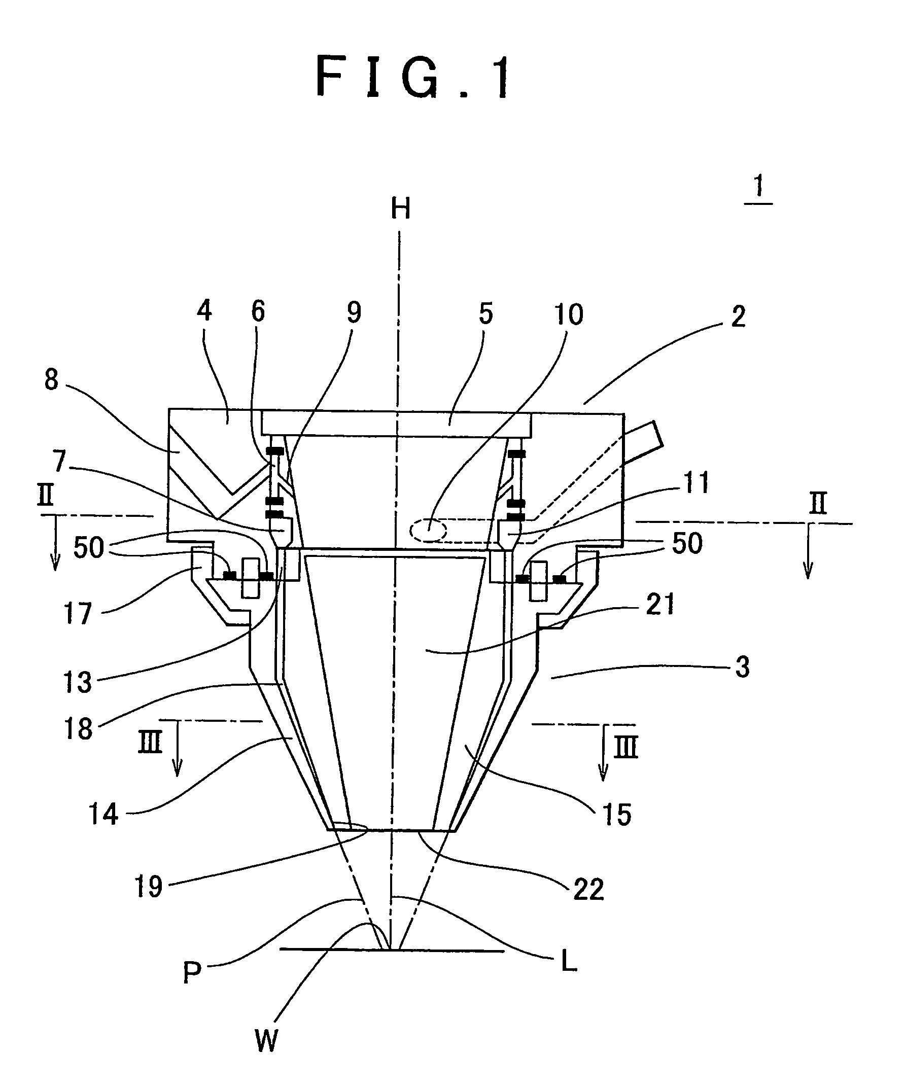
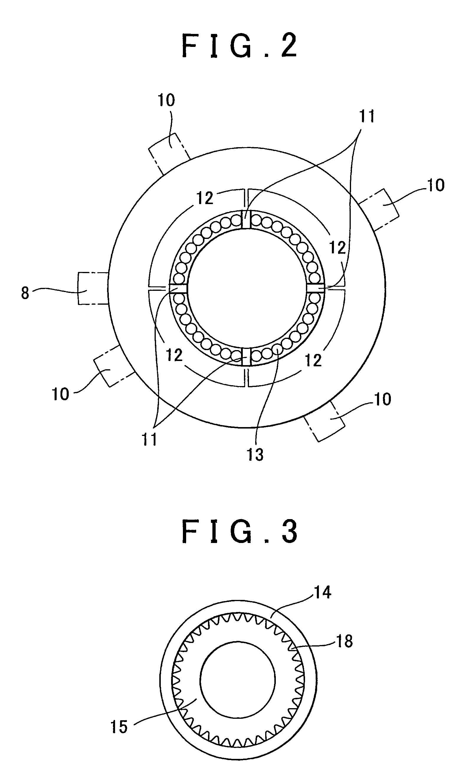
[0039]Hereafter, an embodiment of the invention will be described with reference to FIGS. 1 to 6. FIG. 1 is a cross sectional view schematically showing an entire structure of a powder metal cladding nozzle. FIG. 2 is a cross sectional view taken along line II-II in FIG. 1. FIG. 3 is a cross sectional view taken along line III-III in FIG. 1. Each of FIGS. 4 and 5 shows an inner side member of a nozzle body portion. FIG. 4 is a cross sectional view of the inner side member and FIG. 5 is a front view of the inner side member viewed from the direction of C. FIG. 6 is a side view of an inner side nozzle member of a nozzle portion.

[0040]A powder metal cladding nozzle 1 includes a cylindrical body portion 2, and a nozzle portion 3 which is coaxially coupled to the body portion 2.

[0041]The body portion 2 includes an outer side member 4 and an inner side member 5 which is fitted in a center space of the outer side member 4. A ring-shaped gas holding space 6, in which inert gas is held, and ...


PUM

PropertyMeasurementUnit
discharge distanceaaaaaaaaaa

Abstract

A powder metal cladding nozzle which is coaxially attached to a laser processing head that irradiates a process portion (W) with a laser beam (L) and that discharges powder metal (P) to a laser beam irradiation portion in the process portion (W). The powder metal cladding nozzle includes a body portion (2) that has a ring-shaped powder metal holding space (7) in which the powder metal (P) is held; and a nozzle portion (3) that is connected to the body portion (2) and that has plural discharge passages (18) which are communicated with the powder metal holding space (7) and which open at an outlet (19) for discharging the powder metal (P). The powder metal holding space (7) is formed in the body portion (2) and is divided into plural powder metal holding regions corresponding to plural supply passages (10) that open into the powder metal holding space (7) and that supply the powder metal (P) to the powder metal holding space (7).

Description

FIELD OF THE INVENTION[0001]The invention relates to a powder metal cladding nozzle which discharges powder metal to a process portion that is irradiated with a laser beam, and which performs cladding on the process portion.BACKGROUND OF THE INVENTION[0002]As a powder metal cladding nozzle, a powder metal cladding nozzle using a laser, shown in FIG. 19, is known (refer to Published Japanese Translation of PCT application, JP-T-10-501463).[0003]A powder metal cladding nozzle 100 shown in FIG. 19 is formed by screwing a rear unit 102 into a front unit 101. The rear unit 102 has a beam passage 103 which extends backward (i.e., upward in FIG. 19) from the front unit 101, and the front unit 101 has an opening 104 at the end of the beam passage 103 such that the axis of the beam passage 103 agrees with the center of the opening 104. A cone-shaped passage 107 is formed between an outer surface 105 of the rear unit 102 fitted in the front unit 101 and an inner surface 106 of the front unit ...

Claims


Application Information

Patent Timeline
Patent Type & Authority Patents(United States)
IPC IPC(8): B23K26/14B23K26/34
CPCB23K26/1411B23K26/144
Inventor SATO, AKIOISHIKAWA, YOSHINORINOWOTNY, STEFFENSCHAREK, SIEGFRIED
Owner FRAUNHOFER GESELLSCHAFT ZUR FOERDERUNG DER ANGEWANDTEN FORSCHUNG EV
Why Eureka
Try Eureka