Vacuum regulating valve

Active Publication Date: 2006-11-30
SMC CORP
View PDF7 Cites 26 Cited by
  • Summary
  • Abstract
  • Description
  • Claims
  • Application Information

AI Technical Summary

Benefits of technology

[0009] Accordingly, this invention is intended to provide a vacuum regulating valve including a valve element having a valve face capable of being

Problems solved by technology

In some cases, the valve element is misaligned slightly with the valve stem owing to unsatisfactory machining accuracy in fabricating the components of the vacuum regulating valve and unsatisfactory assembling accuracy in assembling those components.
If the valve element is thus sligh

Method used


Image

  • Vacuum regulating valve
  • Vacuum regulating valve
  • Vacuum regulating valve

Examples


Embodiment Construction

[0021] The detailed description set forth below in connection with the appended drawings is intended as a description of presently preferred embodiments of the invention and is not intended to represent the only forms in which the present invention may be constructed and or utilized.

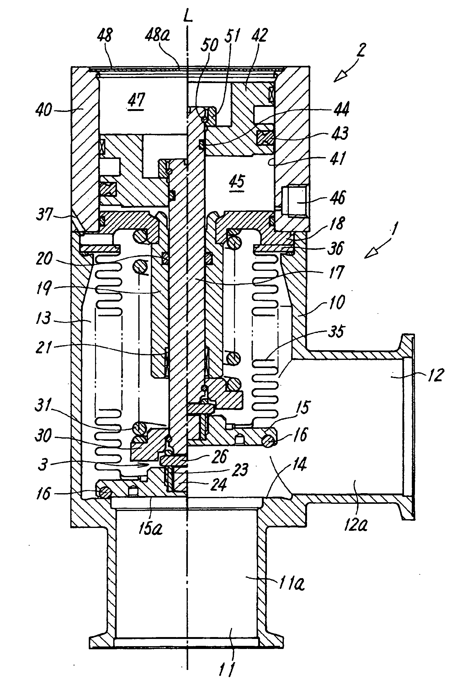
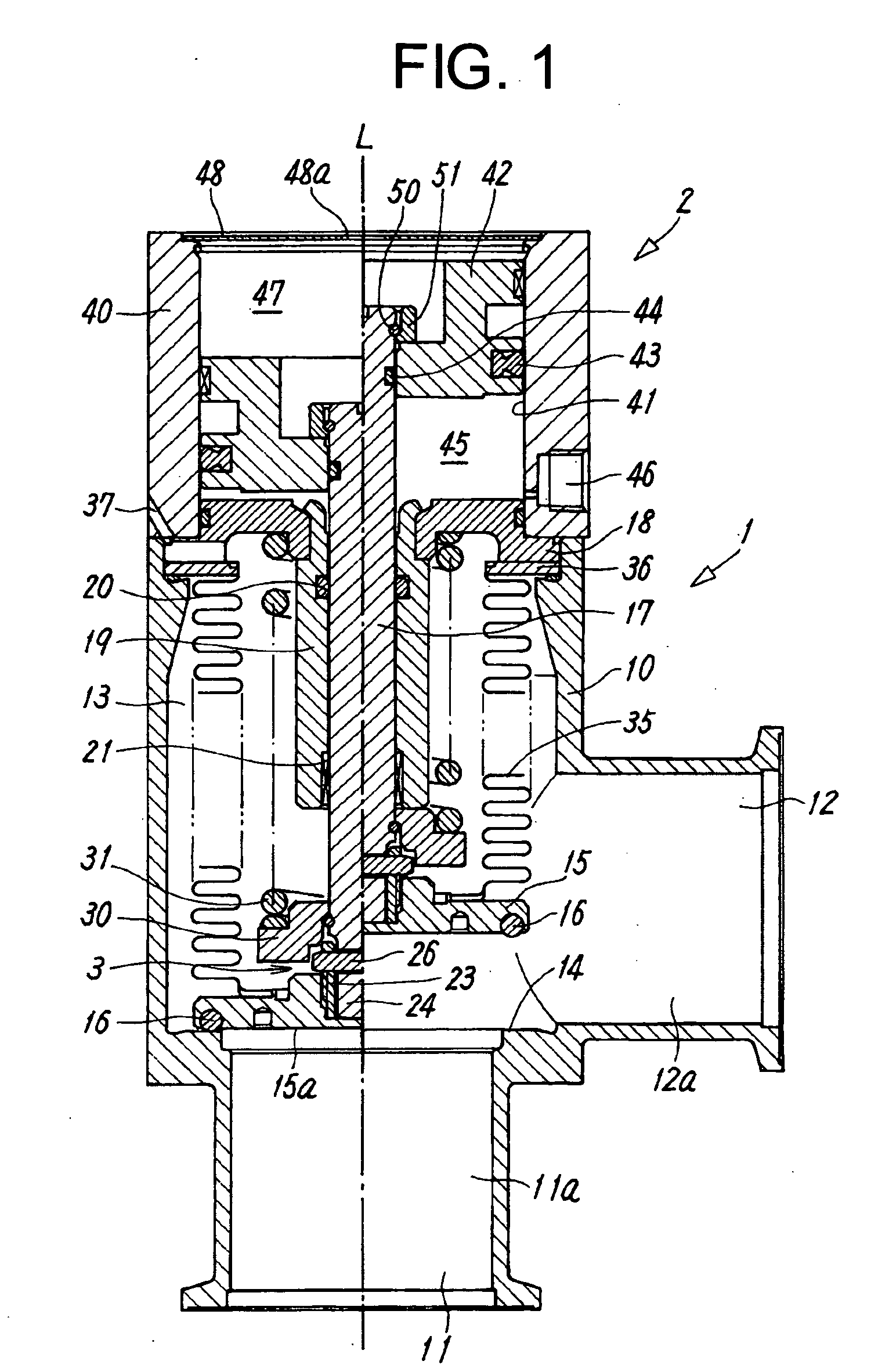
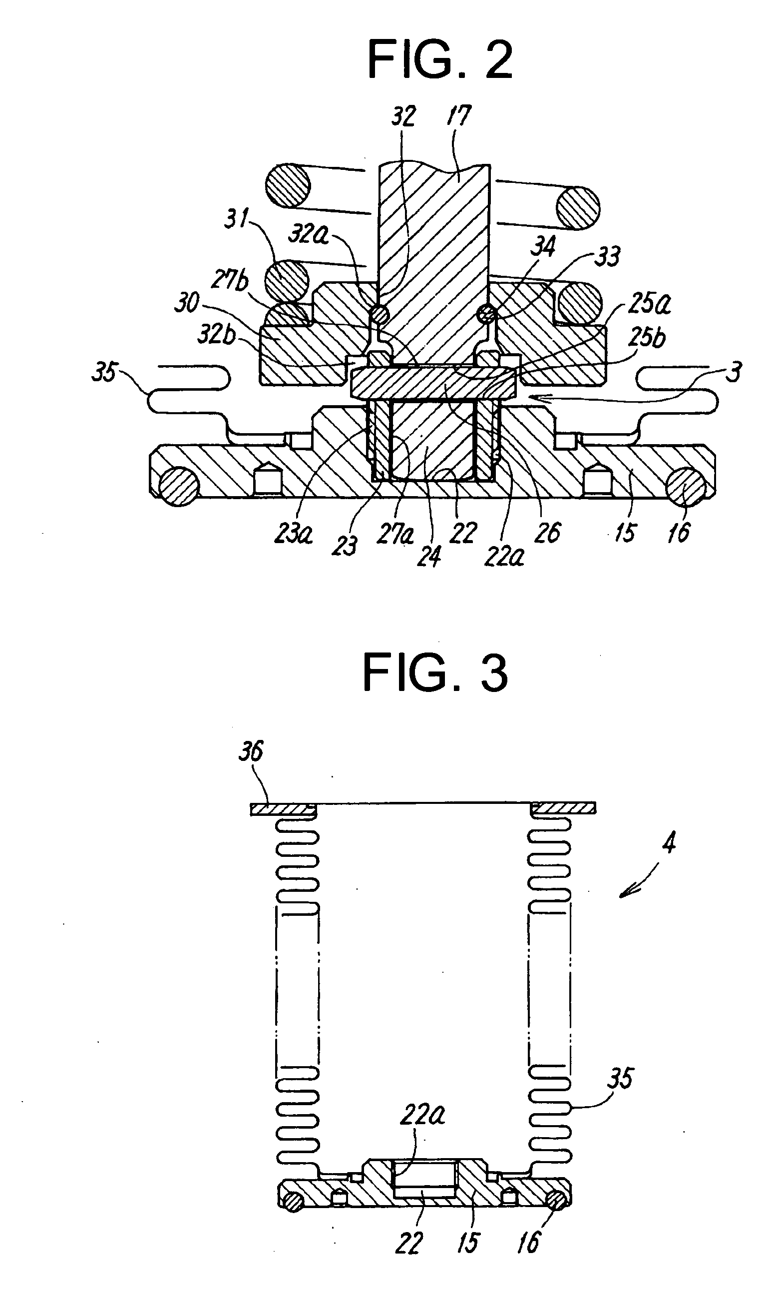
[0022] Referring to FIGS. 1 to 3 showing a vacuum regulating valve in a preferred embodiment according to the present invention, the vacuum regulating valve includes a main valve unit 1 provided with a passage, a valve seat 14 placed in the passage and a poppet type valve element 15 to be seated on and separated from the valve seat to open and close the vacuum regulating valve, and a cylinder actuator 2 for operating the valve element 15. The main valve unit 1 and the cylinder actuator 2 are joined together in alignment with the center axis L of the vacuum regulating valve.

[0023] The main valve unit 1 has a hollow valve body 10 of a shape substantially resembling a rectangular prism or a circular cylin...


PUM


Abstract

A vacuum regulating valve has a poppet type valve element supported so as to be brought into uniformly close contact with a valve seat disposed in a passage connecting two main ports. The valve element is connected to a valve stem by a connecting mechanism that allows the valve element to tilt relative to the valve stem. A piston included in a cylinder actuator moves the valve stem axially.

Description

CROSS-REFERENCES TO RELATED APPLICATIONS [0001] The present application is related to the Japanese Patent Application No. 2005-156121, filed May 27, 2005, the entire disclosure of which is expressly incorporated by reference herein. BACKGROUND OF THE INVENTION [0002] (1) Field of the Invention [0003] The present invention relates to a vacuum regulating valve for use in reducing the pressure of a vacuum chamber included in a physiochemical system, such as a semiconductor device fabricating system, for processing a workpiece by a chemical process. [0004] (2) Description of the Related Art [0005] A semiconductor substrate is subjected to a film forming process using process gasses in a vacuum chamber included in a semiconductor fabricating system to form a film on a surface of the semiconductor substrate. A vacuum regulating valve disclosed in, for example, JP-A-8-285132 is used to regulate a vacuum created in a vacuum chamber during an evacuating process for reducing pressure in the v...

Claims


Application Information

Patent Timeline
IPC IPC(8): F16K31/00
CPCF16K51/02F16K1/48
Inventor KANZAKA, IKUOSAKURAI, TOYONOBU
Owner SMC CORP
Why Eureka
Try Eureka