
Semiconductor temperature sensor capable of adjusting sensed temperature

Inactive Publication Date: 2006-11-30
SAMSUNG ELECTRONICS CO LTD
View PDF8 Cites 15 Cited by
  • Summary
  • Abstract
  • Description
  • Claims
  • Application Information

AI Technical Summary

Benefits of technology

[0035] In another embodiment, the offset control circuit comprises: fifth through eighth PMOS transistors having respective sources connected to the voltage source; fifth and sixth NMOS transistors connected in series between the fifth PMOS transistor and the ground source; seventh and eighth NMOS transistors connected in series between the sixth PMOS transistor and the ground source; ninth and tenth NMOS transistors connected in series between the seventh PMOS transistor and the ground source; and
[0036] eleventh and twelfth NMOS transistors connected in series between the eighth PMOS transistor and the ground source, wherein gates of the fifth and sixth PMOS transistors are connected to a connection node of the fifth PMOS transistor and the fifth NMOS transistor, gates of the seventh and eighth PMOS transistors are connected to a connection node of the eighth PMOS transistor and the eleventh NMOS transistor, an output signal of the adjustment amount determiner is transmitted to gates of the fifth, seventh, ninth, and eleventh NMOS transistors, the second control signal is transmitted to gates of the sixth and twelfth NMOS transistors, the first control signal is transmitted to

Problems solved by technology

For example, dynamic random access memories (DRAMs) must periodically refresh data stored in memory cells therein because the data is lost over time due to a leakage current from capacitors included in memory cells.
A refresh cycle that is to short results in an unnecessary waste of current, and a refresh cycle that is too long results in data being lost.
However, since ΔT1 and ΔT2 are different values, the sensed temperature cannot be linearly adjusted through resistance control.

Method used


Image

  • Semiconductor temperature sensor capable of adjusting sensed temperature
  • Semiconductor temperature sensor capable of adjusting sensed temperature
  • Semiconductor temperature sensor capable of adjusting sensed temperature

Examples


Embodiment Construction

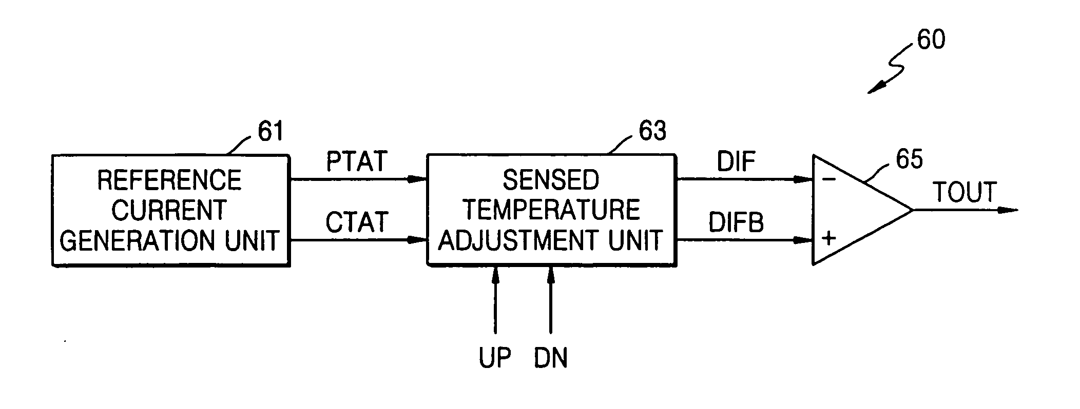
[0052] The present invention will now be described more fully with reference to the accompanying drawings, in which exemplary embodiments of the invention are shown. The invention may, however, be embodied in many different forms and should not be construed as being limited to the embodiments set forth therein; rather, these embodiments are provided so that this disclosure will be thorough and complete. Like reference numerals in the drawings denote like elements, and thus their description will be omitted.

[0053]FIG. 6 is a block diagram of a temperature sensor 60 according to an embodiment of the present invention. The temperature sensor 60 includes a reference current generation unit 61, a sensed temperature adjustment unit 63, and a differential amplification unit 65.

[0054] The reference current generation unit 61 generates a proportional-to-absolute temperature (PTAT) current and a conversely-proportional-to-absolute temperature (CTAT) current. The sensed temperature adjustmen...


PUM


Abstract

A temperature sensor can linearly adjust sensed temperature. The temperature sensor includes: a current generation circuit which generates a proportional-to-absolute temperature (PTAT) current and a conversely-proportional-to-absolute temperature (CTAT) current; and a temperature sensing unit which compares the PTAT current with the CTAT current, senses a temperature at which the PTAT current and the CTAT current are equal, increases the sensed temperature by reducing the PTAT current in response to a first control signal for controlling the sensed temperature to increase, decreases the sensed temperature by increasing the PTAT current in response to a second control signal for controlling the sensed temperature to decrease, and determines an adjustment amount of the sensed temperature which is increased or decreased in response to a third control signal for indicating the adjustment amount.

Description

BACKGROUND OF THE INVENTION [0001] This application claims the priority of Korean Patent Application No. 10-2005-0044246, filed on May 25, 2005, in the Korean Intellectual Property Office, the disclosure of which is incorporated herein in its entirety by reference. [0002] 1. Field of the Invention [0003] The present invention relates to a semiconductor device, and more particularly, to a semiconductor temperature sensor capable of sensing temperature of a semiconductor device and capable of adjusting the sensed temperature. [0004] 2. Description of the Related Art [0005] Temperature sensors are used to sense ambient operational temperature of a circuit or device. They are particularly applicable when there is a need for adjusting operating conditions of circuit blocks within an integrated circuit in response to a change in ambient temperature. [0006] For example, dynamic random access memories (DRAMs) must periodically refresh data stored in memory cells therein because the data is ...

Claims


Application Information

Patent Timeline
IPC IPC(8): H01L31/058G05F3/16G05F3/20
CPCG05F3/30G01K7/01G11C7/04G11C11/40626H03F3/45
Inventor KIM, YONG-JUN
Owner SAMSUNG ELECTRONICS CO LTD
Features
  • Generate Ideas
  • Intellectual Property
  • Life Sciences
  • Materials
  • Tech Scout
  • Unparalleled Data Quality
  • Higher Quality Content
  • 60% Fewer Hallucinations
Learn More