
Thermocouple Measurement Circuit

a measurement circuit and thermocouple technology, applied in the field of temperature measurement circuits, can solve the problems of thermal damage to healthy tissue adjacent to the operative site, undesirable collateral damage to tissue, and tissue sealing or fusion, and achieve the effect of easy addition

Inactive Publication Date: 2008-05-29
COVIDIEN AG
View PDF98 Cites 117 Cited by
  • Summary
  • Abstract
  • Description
  • Claims
  • Application Information

AI Technical Summary

Benefits of technology

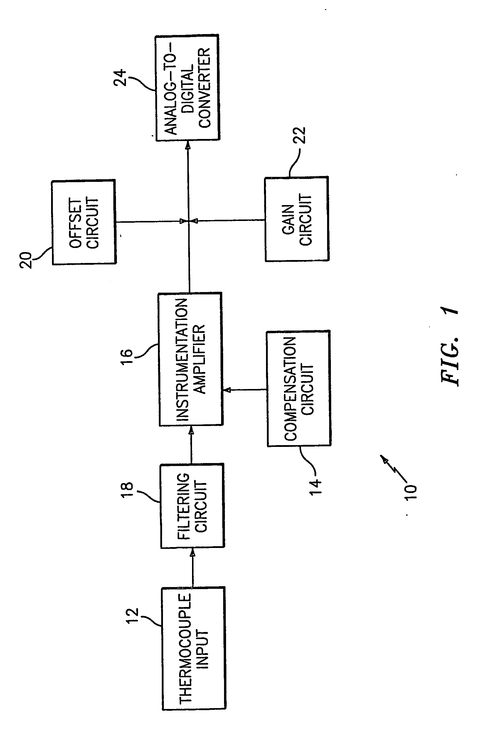
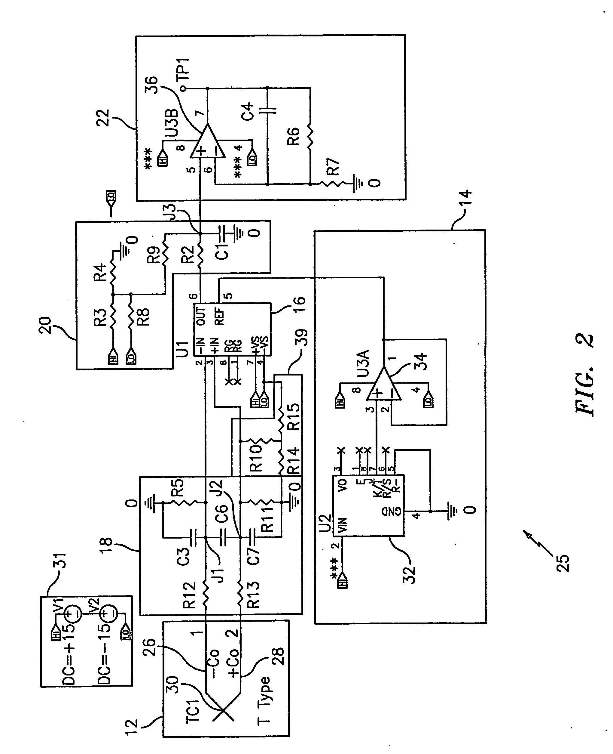
[0011]A thermocouple measurement circuit for sensing a temperature at a measuring point is provided. The thermocouple measurement circuit according to embodiments of the present invention employs an instrumentation amplifier for accurately summing a thermocouple voltage with a cold junction compensation offset to produce a voltage proportional to the temperature sensed. Advantageously, the use of an instrumentation amplifier allows common mode and differential filtering to be easily added for various noise conditions.

Problems solved by technology

One of the issues associated with electrosurgical sealing or fusion of tissue is undesirable collateral damage to tissue due to the various thermal effects associated with electrosurgically energizing tissue.
Healthy tissue adjacent to the operative site may become thermally damaged if too much heat is allowed to build up at the operative site or adjacent the sealing surfaces.
For example, during sealing, the heat may conduct or spread to the adjacent tissue and cause a significant region of tissue necrosis.
Another issue associated with electrosurgical tissue sealing or tissue fusion is the buildup of eschar on the surgical instrument.
Surgical tools often lose effectiveness when coated with eschar.
However, thermocouples alone are not accurate and required compensation circuitry to achieve a desired level of accuracy.

Method used


Image

  • Thermocouple Measurement Circuit
  • Thermocouple Measurement Circuit
  • Thermocouple Measurement Circuit

Examples


Embodiment Construction

[0020]Embodiments of the present invention will be described herein below with reference to the accompanying drawings. In the following description, well-known functions or constructions are not described in detail to avoid obscuring the invention in unnecessary detail.

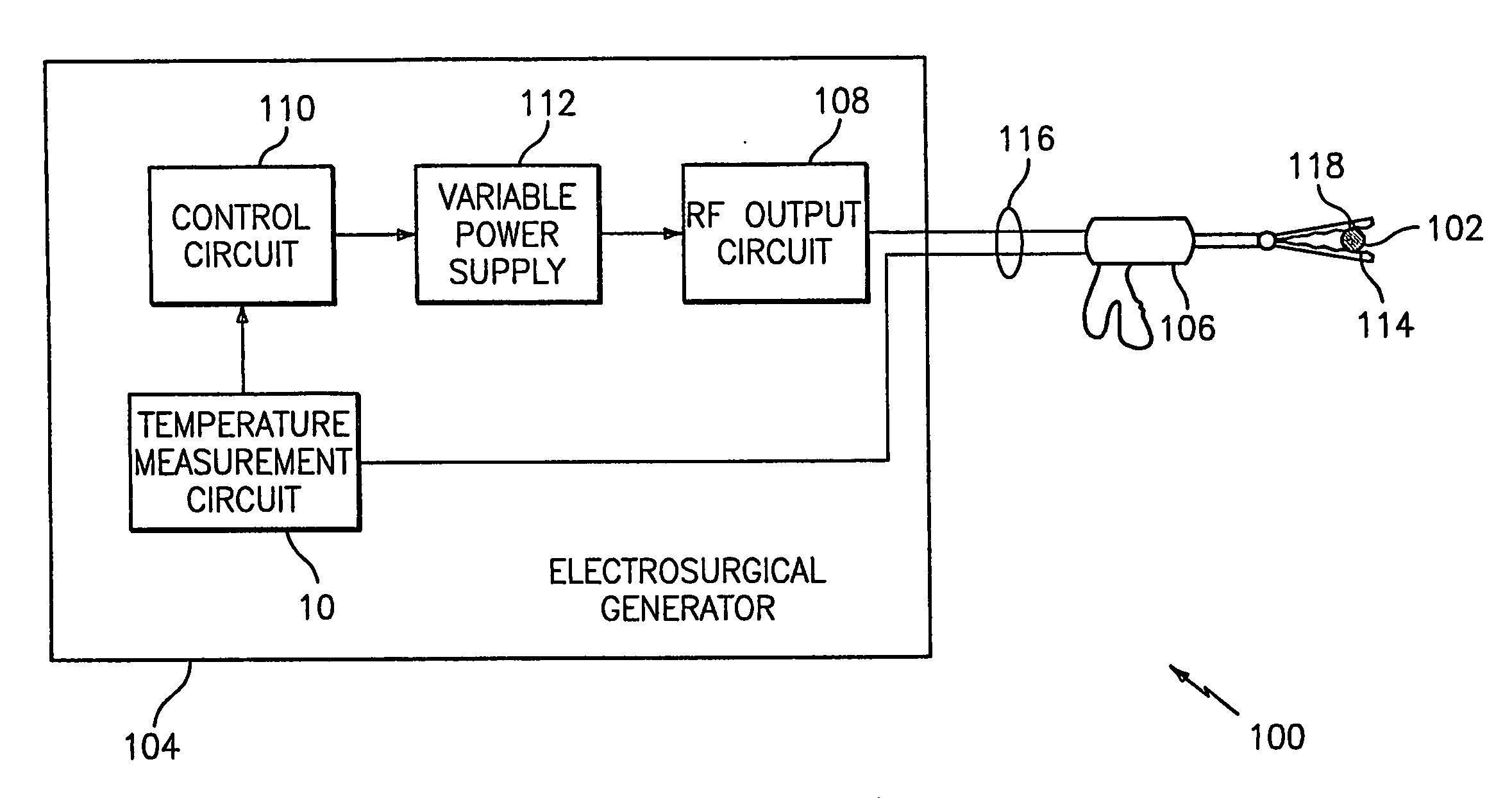
[0021]Referring to FIG. 1, a thermocouple measurement circuit 10 is provided. The thermocouple measurement circuit 10 generally includes a thermocouple input 12 for sensing a temperature of a measuring point, a compensation circuit 14 for compensating thermocouple effects of junctions of the thermocouple 12 and an instrumentation amplifier 16 for summing an output of the thermocouple and an output of the compensation circuit and outputting a voltage indicative of the temperature sensed. The thermocouple measurement circuit 10 may also include a filtering circuit 18 for eliminating noise from the thermocouple input 12 and an offset 20 and gain 22 circuit for scaling an output of the thermocouple measurement circuit 10....


PUM


Abstract

A thermocouple measuring circuit for sensing a temperature at a measuring point is provided. The thermocouple measurement circuit (12) includes a thermocouple input for sensing a temperature at a measuring point, a compensation circuit (14) for compensating thermocouple effects of junctions of the thermocouple, and an instrumentation amplifier (16) for summing an output of the thermocouple and an output of the compensation circuit and outputting a voltage indicative of the temperature sensed, wherein the output of the compensation circuit is a reference voltage for the output of the instrumentation amplifier. Various embodiments of the thermocouple measurement circuit may be employed in electrosurgical generators for controlling output power dependent on temperature conditions.

Description

BACKGROUND[0001]1. Technical Field[0002]The present invention is directed to a temperature measurement circuit, and, in particular, to a thermocouple measurement circuit employed in a control circuit for an electrosurgical generator.[0003]2. Description of the Related Art[0004]Electrosurgical generators are employed by surgeons in conjunction with an electrosurgical tool to cut, coagulate, desiccate and / or seal patient tissue. High frequency electrical energy, e.g., radio frequency (RF) energy, is produced by the electrosurgical generator and applied to the tissue by the electrosurgical tool. Both monopolar and bipolar configurations are commonly used during electrosurgical procedures.[0005]Electrosurgical generators typically include power supply circuits, front panel interface circuits, and RF output stage circuits. Many electrical designs for electrosurgical generators are known in the field. In certain electrosurgical generator designs, the RF output stage can be adjusted to con...

Claims


Application Information

Patent Timeline
IPC IPC(8): A61B18/18G01K7/13
CPCG01K7/13
Inventor BLAHA, DEREK M.
Owner COVIDIEN AG
Learn More