Remote thermostat for room air conditioner

a remote thermostat and room air conditioner technology, applied in the direction of domestic cooling apparatus, heating types, instruments, etc., can solve the problems of overcooling of the room, unit fan not working, temperature sensor typically located in the air intak

Inactive Publication Date: 2005-01-25
ROTONDO JOHN A
View PDF7 Cites 126 Cited by
  • Summary
  • Abstract
  • Description
  • Claims
  • Application Information

AI Technical Summary

Benefits of technology

Accordingly, it is an object of the present invention to provide an air conditioner control assembly for use with a room air conditioner which can be used with inexpensive units and / or with units already owned by the user.
Another object of the present invention is to provide an air conditioner control assembly having the above characteristics and which accurately controls the temperature within the room.
A further object of the present invention is to provide an air conditioner control assembly having the above characteristics and which is efficient from an energy usage standpoint and does not cause needless noise.
Yet still a further object of the present invention is to provide an air conditioner control assembly having the above characteristics and which allows for automatic set-back control to provide improved comfort control and energy conservation.
Still a further object of the present invention is to provide an air conditioner control assembly having the above characteristics and which incorporates safety features that inhibit potential fire and overload of the control assembly.

Problems solved by technology

One such disadvantage is that while the refrigerant compressor starts and stops to regulate the temperature of the room, the unit's fan does not.
This thermostatic control method is inefficient from an energy usage standpoint, causes needless noise, and may result in overcooling of the room if, for example, it becomes cooler outdoors than the desired indoor temperature.
Another disadvantage of traditional thermostatic control mechanisms is that the temperature sensor is typically located in the air intake.
While some traditional window-type air conditioners do include some sort of advanced thermostatic controls which do stop and start the fan as an option, it is only the newest and most expensive units which do so.
However, this is also flawed since this thermostat is designed to measure the temperature of air passing by it.
When the fan is off the unit is slow to respond to temperature demand and as a result does not work well.
While U.S. Pat. Nos. 3,486,081 and 3,785,165 did obviate many of the above-described problems associated with the prior art, numerous problems with the prior art were not addressed thereby.
One such problem concerns the lack of an automatic “set-back” function.
The need to manually alter the regulated temperature is subject to the human failure of forgetting to change the thermostatic setting whereby cost savings are lost.
Also, manual alteration of the regulated temperature is not entirely satisfactory since the dwelling will be uncomfortably cool in the morning before it is manually reset and, due to the lag time of typical heating systems, time is required for the temperature of the dwelling to rise to a comfortable level for normal daytime activities.
While automatic set-back has been provided by thermostats used in conjunction with higher-scale, feature-rich HVAC systems, such features have never been incorporated in the retro-fit type thermostatic control device which can be used with traditional window-type room air conditioners with which the present application is concerned.
Another problem with the systems disclosed in the above-referenced patents relates the lack of important safety features that inhibit potential fire and use of the device on an air conditioner of a size too large for the intended use.
There is nothing preventing a user from plugging an air conditioner twice the size of the units' rating into the thermostatic control device.
This breaker could require two or three more times the power to cause it to go on safety and as a result the prior art devices would receive more current than they are designed to receive and subsequently fail.
Another condition that can happen is that the air conditioner itself could fail and cause a short circuit.
The short may not be enough to cause the main circuit breaker to fail, but just enough to overpower the device and cause a catastrophic failure (i.e., a fire).

Method used


Image

  • Remote thermostat for room air conditioner
  • Remote thermostat for room air conditioner
  • Remote thermostat for room air conditioner

Examples


Embodiment Construction

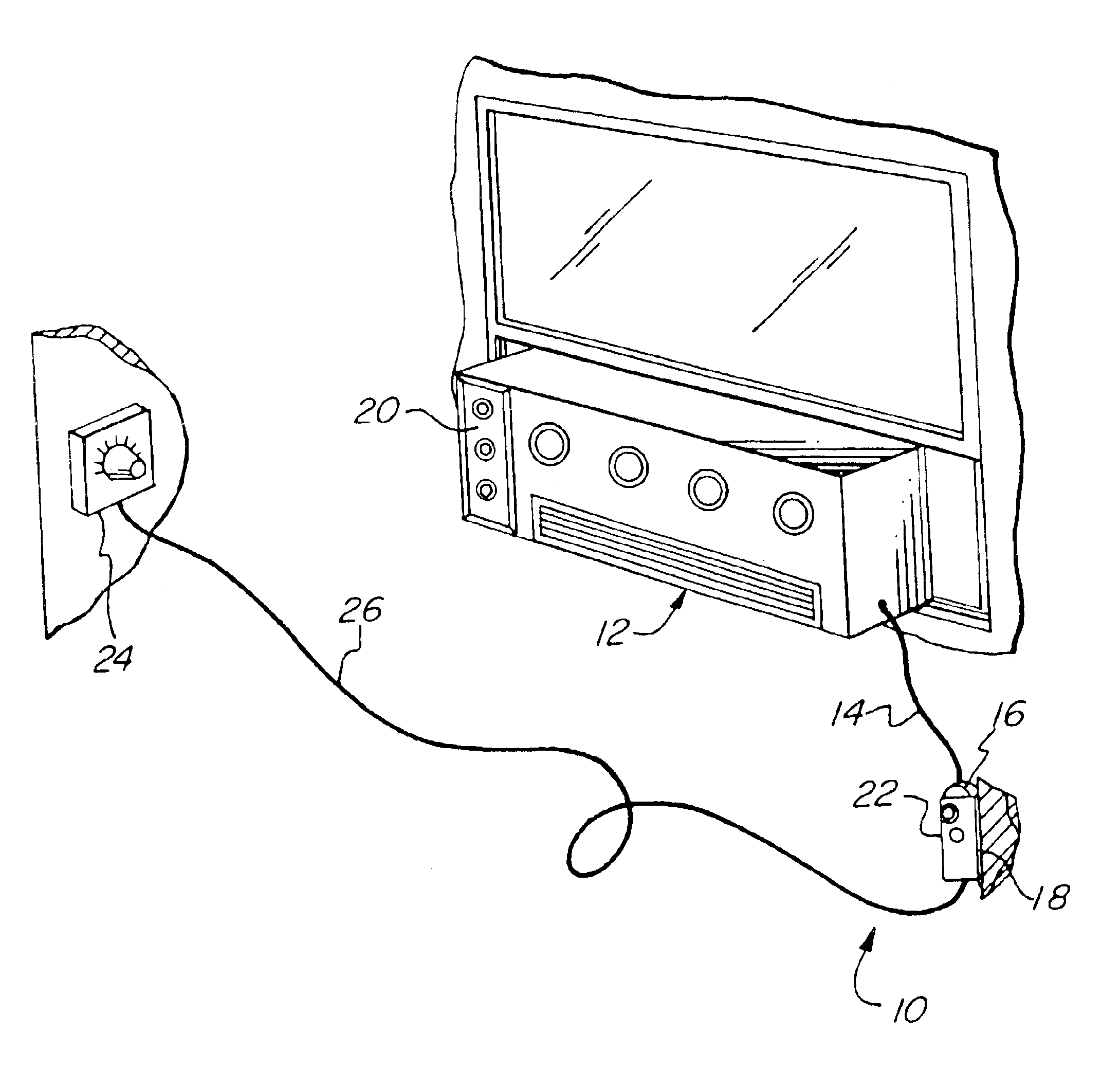
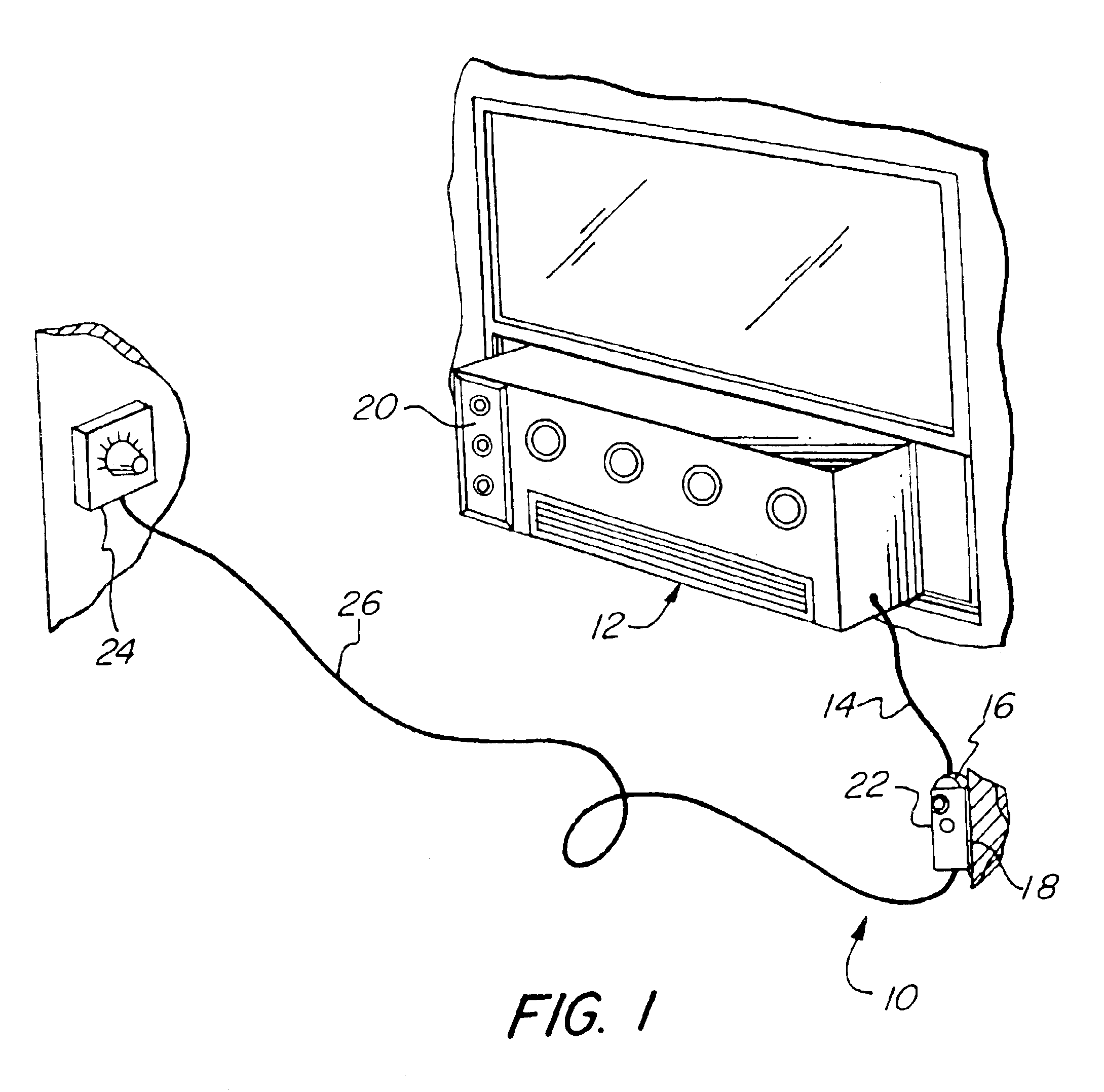
Referring to FIG. 1, an air conditioner control assembly 10 for a room air conditioner 12 mounted in a window in accordance with the present invention is shown. The room air conditioner 12 has a power line 14 provided with a male plug 16 which normally would be inserted in an typical AC power socket 18. The room air conditioner 12 may or may not be provided with thermostatic controls 20 of its own as is known in the art. If such thermostatic controls 20 are provided, they will be set to a temperature lower than a lowest desired room temperature, so as not to interfere with operation of air conditioner control assembly 10.

Air conditioner control assembly 10 includes a control unit 22 and a remote thermostat 24 connected to control unit 22. Remote thermostat 24 may be connected to control unit 22 via a wire 26, typically a low voltage type wire, or may be wireless. Wire 26 may be of substantially length, it being recognized that it is desirable for wire 26 to have sufficient length to...


PUM


Abstract

An air conditioner control assembly for use with a room air conditioner having an electrical plug adapted to be plugged into an electrical socket in order to supply electrical power to the air conditioner is provided. The air conditioner control assembly includes a control unit having an electrical plug adapted to be plugged into an electrical power socket in a home, an electrical socket adapted to receive the electrical plug of the air conditioner, and a relay electrically connected between the two to selectively relay electrical power from the electrical power socket in a home to the air conditioner in response to a control signal. A thermostat located remotely from the control unit and from the air conditioner is electrically connected to the control unit, the thermostat generating the control signals to which the relay is responsive as a function of temperature sensed by the thermostat and time of day.

Description

FIELD OF THE INVENTIONThe present invention relates to a thermostatic control device which can be used with traditional window-type room air conditioners to provide enhanced temperature control thereof.BACKGROUND OF THE INVENTIONTraditional window-type room air conditioners typically include a very basic thermostatic control mechanism which suffers from a number of disadvantages. One such disadvantage is that while the refrigerant compressor starts and stops to regulate the temperature of the room, the unit's fan does not. Thus, when the room is too warm the fan will continue to run even if the desired room temperature has been met. This thermostatic control method is inefficient from an energy usage standpoint, causes needless noise, and may result in overcooling of the room if, for example, it becomes cooler outdoors than the desired indoor temperature.Another disadvantage of traditional thermostatic control mechanisms is that the temperature sensor is typically located in the air...

Claims


Application Information

Patent Timeline
Patent Type & Authority Patents(United States)
IPC IPC(8): F24F11/00
CPCF24F11/0012F24F2011/0091F24F2011/0047F24F11/30F24F2110/10F24F2140/60F24F11/52F24F11/56F24F11/88F24F11/46F24F11/523
Inventor ROTONDO, JOHN A.
Owner ROTONDO JOHN A
Why Eureka
Try Eureka