Supercharge Your Innovation With Domain-Expert AI Agents!

Raster image processing method, image processing method, rasterizing device, and image forming device

a technology of rasterizing device and image, which is applied in the direction of digitally marking record carriers, digital output to print units, instruments, etc., can solve the problems of large amount of information of copied images, large memory space consumed by the computer, and inability to cope with printing images. , to achieve the effect of short processing time and small storage capacity

Inactive Publication Date: 2006-11-30
RICOH KK
View PDF13 Cites 5 Cited by
  • Summary
  • Abstract
  • Description
  • Claims
  • Application Information

AI Technical Summary

Benefits of technology

[0019] According to one aspect of the invention, there is provided an improved raster image processing method in which the above-mentioned problems are eliminated.
[0020] According to one aspect of the invention, there is provided one of a raster image processing method, an image processing method, a rasterizing device, and an image forming device which are adapted for correcting a deviation of the image in image formation processing with a small storage capacity and in a short processing time.
[0023] According to the embodiments of the invention, it is possible to provide the raster image processing method, the image processing method, the rasterizing device, and the image forming device which can correct a deviation of the image in image formation processing with a small storage capacity and a short processing time.

Problems solved by technology

In such computers, the above-mentioned print image has a large amount of information, so that most of the address space (memory space) of the CPU may be consumed.
Thus, it is difficult for the computer to deal with the print image.
However, the amount of information of the copied image is very large, and the processing time needed is also long.
For this reason, there is a problem that the processing time becomes long.
However, the problem that the cost for storage in the case of the semiconductor memory is higher than in the case of the HDD remains unsolved.
The sequential access to the memory cannot be performed, and the memory cache function does not work effectively.
As a result, the processing time needed for image formation becomes long.

Method used


Image

  • Raster image processing method, image processing method, rasterizing device, and image forming device
  • Raster image processing method, image processing method, rasterizing device, and image forming device
  • Raster image processing method, image processing method, rasterizing device, and image forming device

Examples


Embodiment Construction

[0051] A description will now be given of an embodiment of the invention with reference to the accompanying drawings.

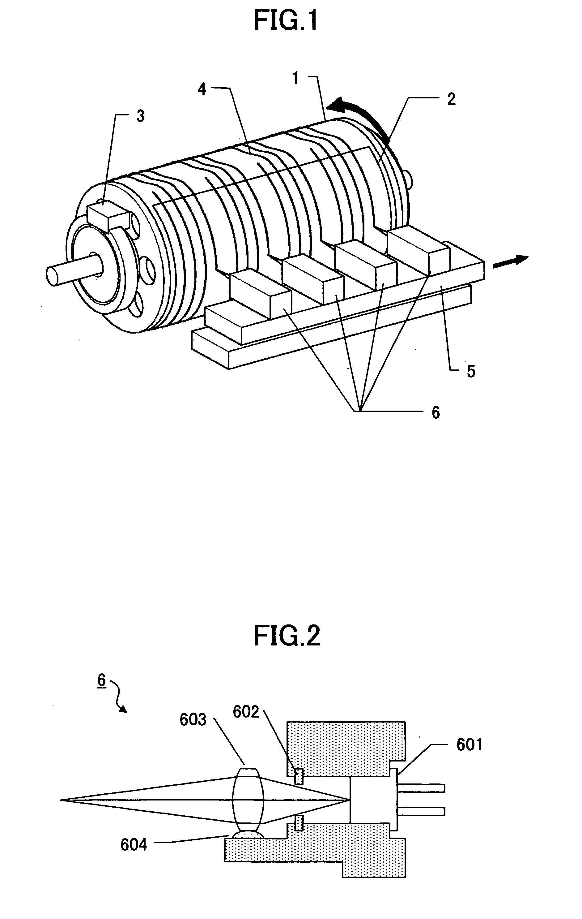
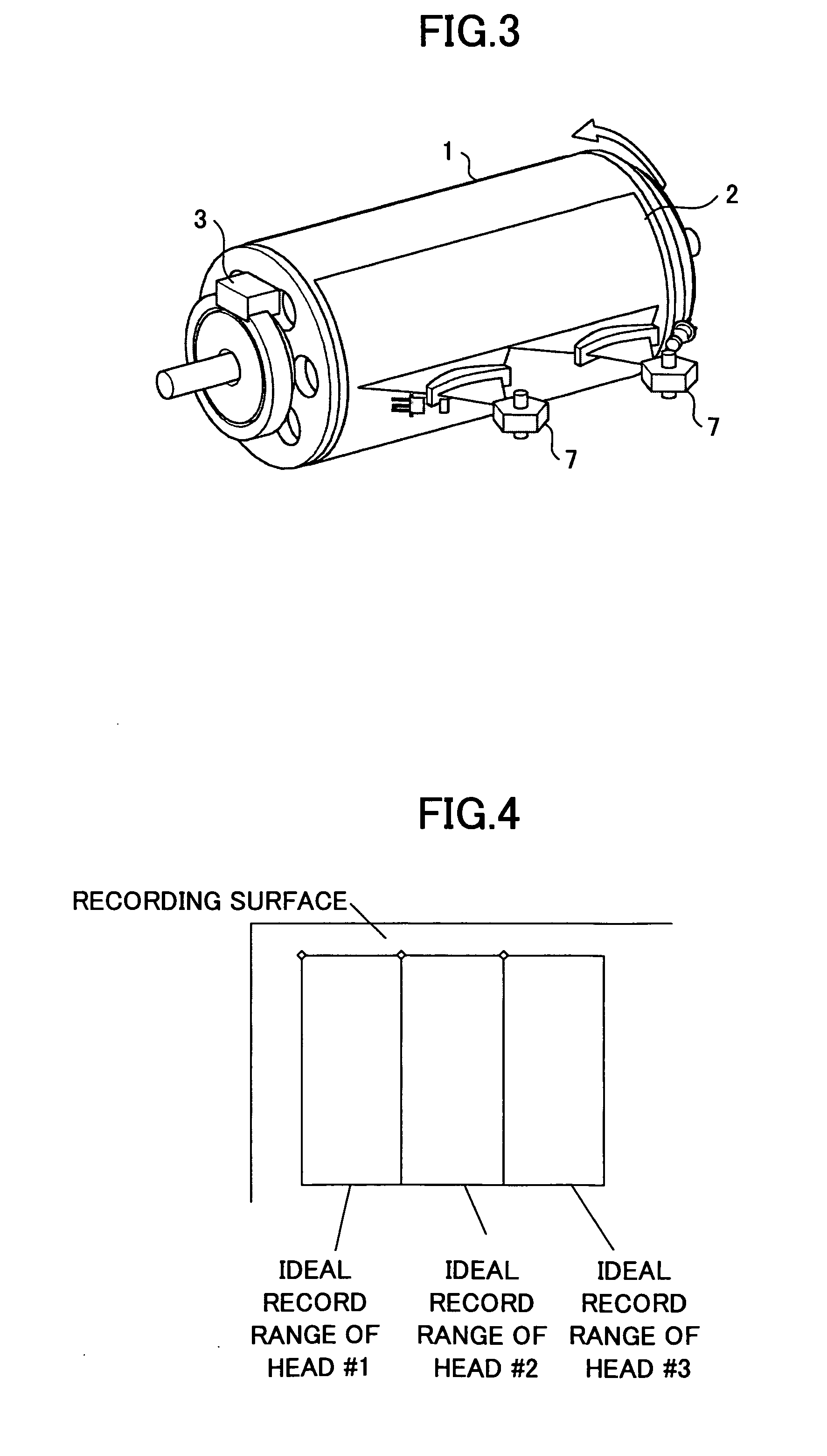
[0052]FIG. 1 shows the composition of an image forming device in an embodiment of the invention. The image forming device of FIG. 1 comprises a drum 1, a recording medium 2, a drum encoder 3, a moving stage 5, and a plurality of recording heads 6.

[0053] The drum 1 is rotated around the central axis of the drum 1 in the direction indicated by the arrow in FIG. 1, by a rotation drive mechanism (not shown). The recording medium 2 is provided on the cylindrical surface of the drum 1. The plurality of recording heads 6 are mounted on the moving stage 5 and this moving stage 5 is moved in the direction indicated by the arrow in FIG. 1, which is parallel to the axial direction of the drum 1.

[0054] As shown in FIG. 1, the four recording heads 6, each of which outputs energy to the recording medium 2, are arranged on the moving stage 5 at intervals of substantially equal di...


PUM


Abstract

A raster image processing method is adapted for a rasterizing device which converts original image data into raster image data suitable for an image forming device having a plurality of recording heads and performing recording of an image on a recording medium using the plurality of recording heads. The original image data is divided into image data elements for areas of the recording medium for the plurality of recording heads to perform the recording of the image respectively. The divided original image data elements are rasterized into the raster image data suitable for the image forming device.

Description

BACKGROUND OF THE INVENTION [0001] 1. Field of the Invention [0002] The present invention generally relates to a raster image processing method, an image processing method, a rasterizing device, and an image forming device. More particularly, the present invention relates to a raster image processing method, an image processing method, a rasterizing device, and an image forming device which are adapted to correct a deviation of an image in image formation processing by a plurality of recording heads. [0003] 2. Description of the Related Art [0004] Japanese Laid-Open Patent Application No. 2004-147260 discloses an image forming device which eases correction of a deviation of each divided image data element when the original image data is divided into a plurality of divided image data elements and an image formation process is performed by using two or more recording heads. [0005] Japanese Laid-Open Patent Application No. 11-291566 discloses a rasterizing method which includes a comma...

Claims


Application Information

Patent Timeline
Patent Type & Authority Applications(United States)
IPC IPC(8): G06F3/12G06F15/00
CPCB41J2/47B41J2/471H04N1/0473H04N1/06H04N2201/04791H04N1/1912H04N1/387H04N2201/0426H04N2201/04787H04N1/0671
Inventor SUZUKI, SHINICHIMORIKAWA, MINORUISHIMA, KAZUMI
Owner RICOH KK
Features
  • R&D
  • Intellectual Property
  • Life Sciences
  • Materials
  • Tech Scout
  • Unparalleled Data Quality
  • Higher Quality Content
  • 60% Fewer Hallucinations
Learn More