Image receiving apparatus and image reproducing apparatus

a technology of image receiving apparatus and reproducing apparatus, which is applied in the direction of simultaneous/sequencial multiple television signal transmission, color television details, television systems, etc., can solve the problems of not being able to know in which conditions the recorded video has been taken, one reproducing device may not be able to correctly convert a video to be reproduced to its own, and the reproducing device cannot be able to reproduce a video taken by another picture-taking device. , to achieve the effect o

Inactive Publication Date: 2006-11-30
SHARP KK
View PDF21 Cites 57 Cited by
  • Summary
  • Abstract
  • Description
  • Claims
  • Application Information

AI Technical Summary

Benefits of technology

[0015] In view of the above problems, an object of the present invention is to provide a video reproducing apparatus and a video receiving apparatus that facilitate viewing / listening in connection with video data including added information for increasing usability of a video data from stereo picture-taking while maintaining compatibility with existing devices.

Problems solved by technology

However, the above conventional technique only adds recording names for identifiers and it is not possible to know in which conditions the recorded video has been taken.
While it would be acceptable on a reproducing device for only reproducing videos taken by certain picture-taking devices, the same reproducing device may not be capable of reproducing a video taken by other picture-taking devices.
However, since reproduced videos of different data formats require different processing methods, one reproducing device may not correctly convert a video to be reproduced to its display format when the video's data format is not known.
Videos taken by the same picture-taking device may not be correctly converted if the display mode of the reproducing device is different, requiring a different processing method.
That is, while there won't be a problem if one picture-taking device corresponds to one reproducing device, the usability of a video taken will be significantly compromised when videos are exchanged between different devices which will require the picture-taking condition to match with the reproducing condition.
Moreover, identifiers are recorded not only in stereo picture-taking but also in monocular picture-taking, but certain modes of recording may make reproduction impossible in other devices.

Method used


Image

  • Image receiving apparatus and image reproducing apparatus
  • Image receiving apparatus and image reproducing apparatus
  • Image receiving apparatus and image reproducing apparatus

Examples


first embodiment

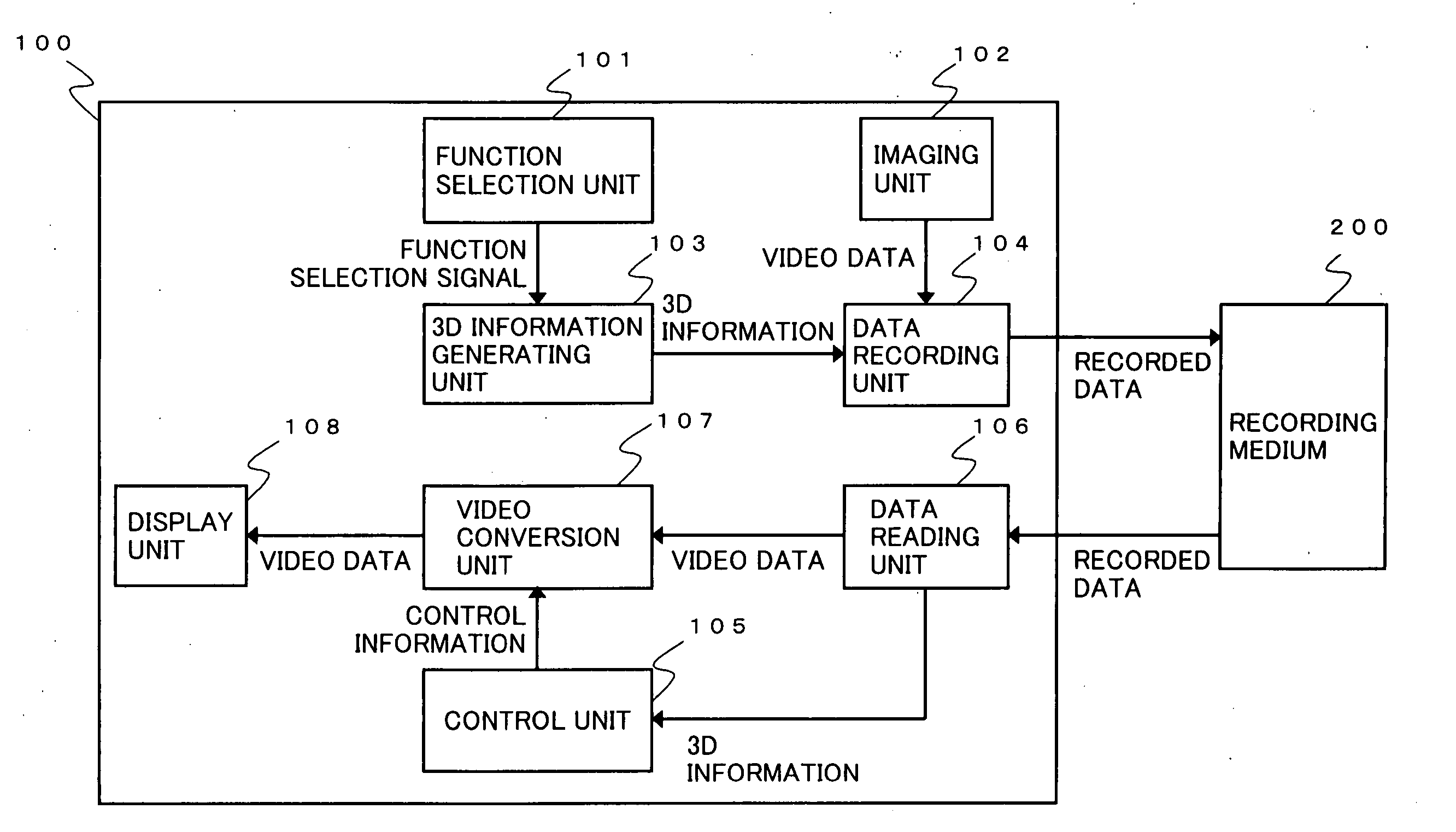
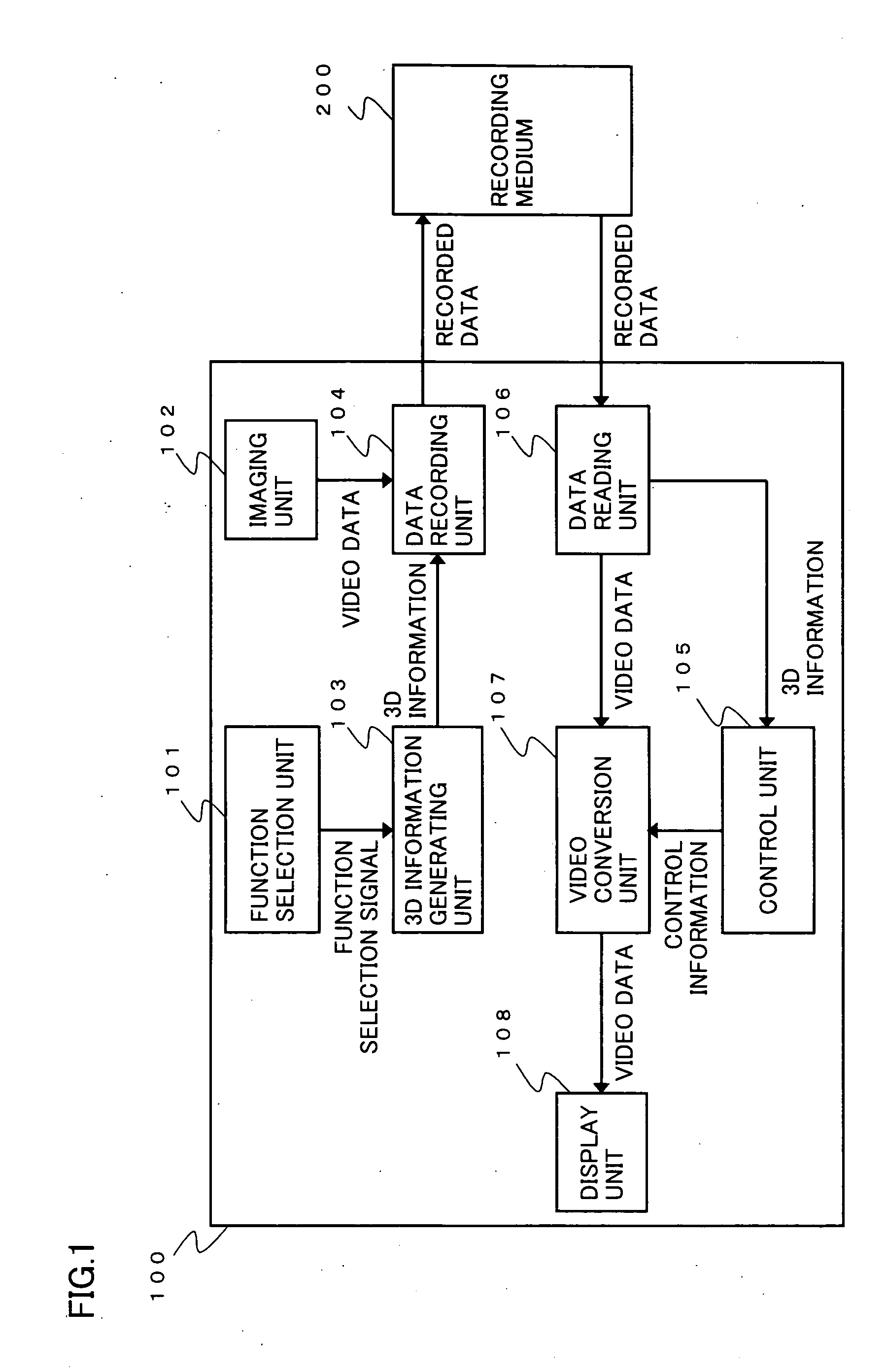
[0044]FIG. 1 is a block diagram showing a configuration of a video recording apparatus 100 according to a first embodiment of the present invention.

[0045] Referring to FIG. 1, video recording apparatus 100 records in a recording medium 200 a video taken from a subject, and reproduces a video recorded in recording medium 200. Thus, video recording apparatus 100 also functions as a video reproducing apparatus.

[0046] Video recording apparatus 100 includes: a function selection unit 101 for selectively switching the picture-taking function between monocular picture-taking and stereo picture-taking; an imaging unit 102 having an imaging element such as a Charge Coupled Device (CCD) and an autofocusing circuit; a 3D information generating unit 103 generating three-dimension information (hereinafter referred to as “3D information”) of a predetermined format; and a data recording unit 104 recording in recording medium 200 video data and 3D information after they have been formatted. Video...

second embodiment

[0077]FIG. 7 shows a video reproduction system where a video transmitting apparatus 140 that transmits video data is connected with a video receiving apparatus 150 that receives the video data via a transmission channel 160 through which video data as well as commands for controlling connected apparatuses are exchanged.

[0078]FIG. 8 is a block diagram showing an exemplary configuration of video transmitting apparatus 140.

[0079] In FIG. 8, like components as in FIG. 1 are designated by like characters and thus will not be described again. Video transmitting apparatus 140 includes a function selection unit 101, an imaging unit 102, a 3D information generating unit 103, a data recording unit 141, a control unit 105, a data reading unit 142, a video conversion unit 107, a display unit 108, a transmission unit 143, a reception unit 145 and a recording medium 200.

[0080] Operations of video transmitting apparatus 140 configured above will now be described. However, the operations since p...

third embodiment

[0126] Description will now be made of creation of a list of video contents recorded in a recording medium 200 mounted on video transmitting apparatus 140 by video receiving apparatus 150 shown in FIG. 11, and of its presentation to the user.

[0127] As an example, the DV format may be used for recording, as above. Further, before video data is recorded in recording medium 200, elements of 3D information that will be required for high-speed searching are recorded in subcode area 304 of FIG. 4 as shown in FIG. 18 and, for a high-speed searching of the recording medium, video transmitting apparatus 140 only transmits subcodes out of data read from recording medium 200 in packet to transmission channel 160.

[0128] Video receiving apparatus 150 receives packets from transmission channel 160 and treats the first time code received as the starting position of the first video content. If a packet contains 3D information, the attribute is 3D, otherwise it is 2D. The starting position of the ...


PUM


Abstract

The present invention relates to a video receiving apparatus receiving, from a communication channel, video data of three-dimensional video taken using binocular parallax and added information for the video data, or to a video reproducing apparatus reading such from a recording medium. The video receiving apparatus or video reproducing apparatus detects added information indicating a predetermined format for three-dimensionally displaying the video data, and three-dimensionally displays video data that conforms to the predetermined format. The video receiving apparatus uses a data reception unit to receive multiplexed data including video data and added information and uses a data separation unit to extract the video data and its added information. A control unit controls a video conversion unit based on the added information to convert the video data to three-dimensional video that conforms to the predetermined format and display it on a display unit.

Description

TECHNICAL FIELD [0001] The present invention relates to a video receiving apparatus to receive and three-dimensionally display video data which has been provided by taking a three-dimensional video using binocular parallax and transmitted via a communication channel, and a video reproducing apparatus to read and three-dimensionally display video data which has been provided by taking a 3D video using binocular parallax and recorded in a recording medium. BACKGROUND ART [0002] Conventionally, stereo video in which a plurality of videos with a parallax for a subject can be separately viewed by the right and left eyes to view the imaged subject three-dimensionally can be taken by a common monocular camera with a stereo adaptor mounted on it for forming a plurality of subject images with different visual points to take a plurality of videos with a parallax on one screen. [0003]FIGS. 20A to 20C are views for explaining videos taken with a stereo adaptor mounted. [0004]FIG. 20A shows a vi...

Claims


Application Information

Patent Timeline
Patent Type & Authority Applications(United States)
IPC IPC(8): H04N7/00H04N7/08H04N5/91H04N7/081H04N13/00H04N13/04
CPCH04N13/004H04N13/0048H04N13/0055H04N13/0059H04N9/8227H04N13/0289H04N13/0454H04N13/0456H04N19/597H04N13/0066H04N13/289H04N13/194H04N13/189H04N13/156H04N13/161H04N13/359H04N13/361H04N13/178H04N13/00
Inventor ITO, MOTOHIROOHARA, KAZUTO
Owner SHARP KK
Why Eureka
Try Eureka