
Photography apparatus, photography method and photography program

Active Publication Date: 2006-11-30
FUJIFILM HLDG CORP +1
View PDF2 Cites 91 Cited by
  • Summary
  • Abstract
  • Description
  • Claims
  • Application Information

AI Technical Summary

Benefits of technology

[0042] According to the first photography apparatus, the first photography method, and the first photography program of the present invention, the weighting parameter for the statistical characteristic quantity representing the lighting condition in the structure in the input through image can be obtained by fitting to the structure in the input through image the model representing the predetermined structure with use of the statistical characteristic quantity or quantities including the statistical characteristic quantity representing the lighting condition and the weighting parameter or parameters therefor. Based on the value of the weighting parameter having been obtained, the auxiliary light source can be controlled so as to cause the condition of lighting for the subject to become appropriate. In this manner, the present invention pays attention to the statistical characteristic quantity representing the lighting condition, and the auxiliary light source is controlled by the appropriate condition according to the weighting parameter corresponding to the statistical characteristic quantity representing the lighting condition for the structure in the input through image. Therefore, the photography can be realized with less effect of black or white compression and contrast caused by shadow.
[0043] According to the second photography apparatus, the second photography method, and the second photography program of the present invention, the weighting parameter for the statistical characteristic quantity representing the lighting condition in the structure in the input through image can be obtained by fitting to the structure in the input through image the model representing the predetermined structure with use of the statistical characteristic quantity or quantities including the statistical characteristic quantity representing the lighting condition and the weighting parameter or parameters therefor. Based on the value of the weighting parameter having been obtained, the warning is carried out in the case where the value of the weighting parameter does not satisfy the predetermined criterion representing the preferable lighting condition. Therefore, a photographer can manually adjust an auxiliary light source in the case where the preferable lighting condition is not obtained. Consequently, the photography can be realized with less effect of black or white compression and contrast caused by shadow.
[0044] In the case where the step (or the means) for detecting the structure in the input through image is added, automatic detection of the structure can be carried out. Therefore, the photography apparatuses become easier to operate.
[0045] In the case where the plurality of models are prepared for the respective properties of the predetermined structure in the present invention while the steps (or the means) are added for obtaining the property of the structure in the input through image and for selecting one of the models in accordance with the property having been obtained, if the weighting parameter is obtained by fitting the selected model to the structure in the input through image, the structure in the input through image can be fit to the model that is more suitable. Therefore, processing accuracy is improved, and the photography can be carried out for a higher quality image.
[0046] In the case where the structure is human face, a human face is a main part of image in many cases. Therefore, the auxiliary light source can be controlled to be optimal for the main part, enabling the photography to be more preferable.

Problems solved by technology

Therefore, once black compression or white compression occurs, information on a part of the compression is missing in an image, and the part cannot be corrected later.

Method used


Image

  • Photography apparatus, photography method and photography program
  • Photography apparatus, photography method and photography program
  • Photography apparatus, photography method and photography program

Examples


Embodiment Construction

[0059] Hereinafter, embodiments of the present invention will be described with reference to the accompanying drawings.

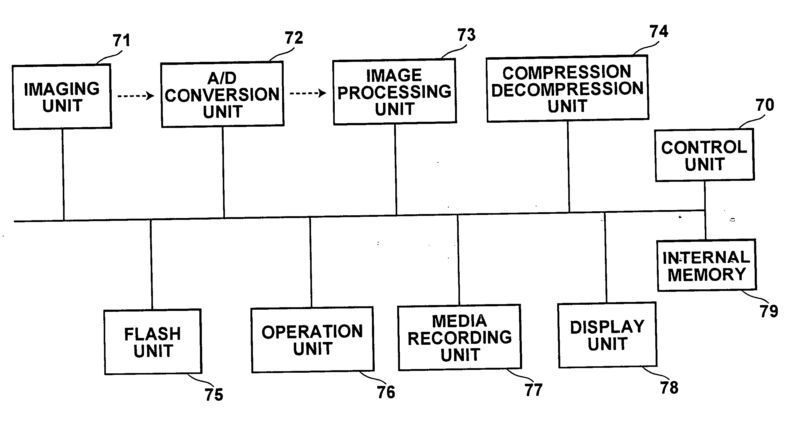
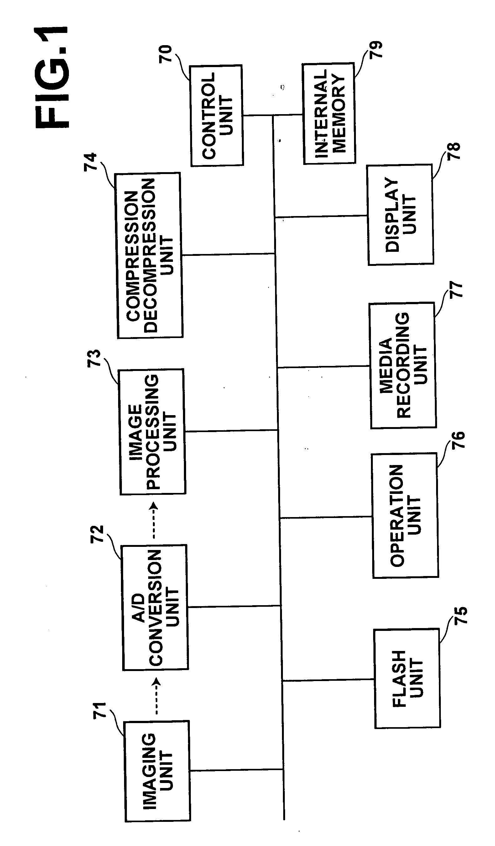
[0060]FIG. 1 shows the configuration of a digital camera as an embodiment of the present invention. As shown in FIG. 1, the digital camera has an imaging unit 71, an A / D conversion unit 72, an image processing unit 73, a compression / decompression unit 74, a flash unit 75, an operation unit 76, a media recording unit 77, a display unit 78, a control unit 70, and an internal memory 79. The imaging unit 71 comprises a lens, an iris, a shutter, a CCD, and the like, and photographs a subject. The A / D conversion unit 72 obtains digital image data by digitizing an analog signal represented by charges stored in the CCD of the imaging unit 71. The image processing unit 73 carries out various kinds of image processing on image data. The compression / decompression unit 74 carries out compression processing on image data to be stored in a memory card, and carries out decompress...


PUM


Abstract

An auxiliary light source such as a flash is controlled for highly accurately reflecting a lighting condition with less effect of a factor other than the lighting condition such as contrasting density caused by shadow or black compression or white compression. For this purpose, a parameter acquisition unit obtains weighting parameters for principal components representing lighting conditions in a face region in an image detected by a face detection unit, by fitting to the detected face region a mathematical model generated according to a method of AAM using a plurality of sample images representing human faces in different lighting conditions. A flash control unit obtains a flash control condition by referring to a reference table according to the parameters, and controls flash light emission according to the control condition.

Description

BACKGROUND OF THE INVENTION [0001] 1. Field of the Invention [0002] The present invention relates to a photography apparatus having a function for controlling light emission from an auxiliary light source such as a flash at the time of photography and to a photography method therefor. The present invention also relates to a program for causing a computer to execute the photography method. [0003] 2. Description of the Related Art [0004] There has been known a camera that enables automatic setting of a flash if necessary by predicting how a shadow appears based on direction and strength of sunlight before photography (see U.S. Pat. No. 6,314,241). The camera described in U.S. Pat. No. 6,314,241 has an imaging device for shadow detection under a glass window located in an upper part of the camera. The camera predicts a manner of appearance of shadow changing with direction of sunlight and weather, based on a position and density of a shadow of a black mark formed in the glass window. T...

Claims


Application Information

Patent Timeline
IPC IPC(8): G03B15/03G03B7/16G03B15/05G03B17/18H04N5/238H04N101/00
CPCG03B15/03G06K9/621G06K9/00248G06V40/165G06V10/7557
Inventor YODA, AKIRAITO, WATARU
Owner FUJIFILM HLDG CORP
Learn More