Rotary vacuum blower

a vacuum blower and rotary technology, applied in the direction of motors, liquid fuel engines, non-positive displacement pumps, etc., can solve the problems of machine still having to be shut down and light fluid leakage between the casings, and achieve the effect of convenient application

Active Publication Date: 2006-11-30
CATTANI SPA
View PDF6 Cites 2 Cited by
  • Summary
  • Abstract
  • Description
  • Claims
  • Application Information

AI Technical Summary

Benefits of technology

[0010] A further advantage is that the invention can easily be applied to machines of known type.
[0011] These aims and advantages and more besides are all attained by the machine of the invention, as it is characterised in the claims that follow.
[0012] The machine comprises an impeller, set in rotation by a motor of known type, provided with blades and closed in a casing which defines a circumferential annular conduit in which the blades turn. The annular conduit exhibits two openings, respectively an induction mouth for aspirating fluid from outside the machine, and a delivery mouth from which the fluid exits from the machine. The machine also comprises a further opening which is neither the induction mouth nor the delivery mouth, afforded on the casing and defining a passage which places an inside of the casing in communication with an outside environment.

Problems solved by technology

However careful the mechanical construction may be, however, it is still inevitable that owing to the difference in pressure between the machine delivery mouth zone and the machine intake mouth zone there is a slight fluid leakage between casing and impeller body, in the opposite direction to the direction determined by the blade action, between the two zones.
Sometimes, however, in the warm seasons, the machine still has to be shut down during long periods of operation.

Method used


Image

  • Rotary vacuum blower
  • Rotary vacuum blower
  • Rotary vacuum blower

Examples


Embodiment Construction

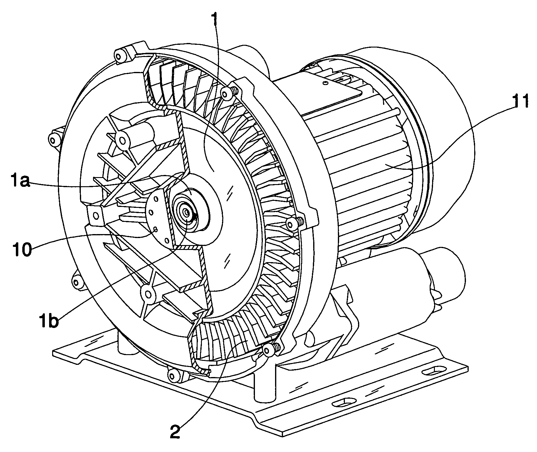
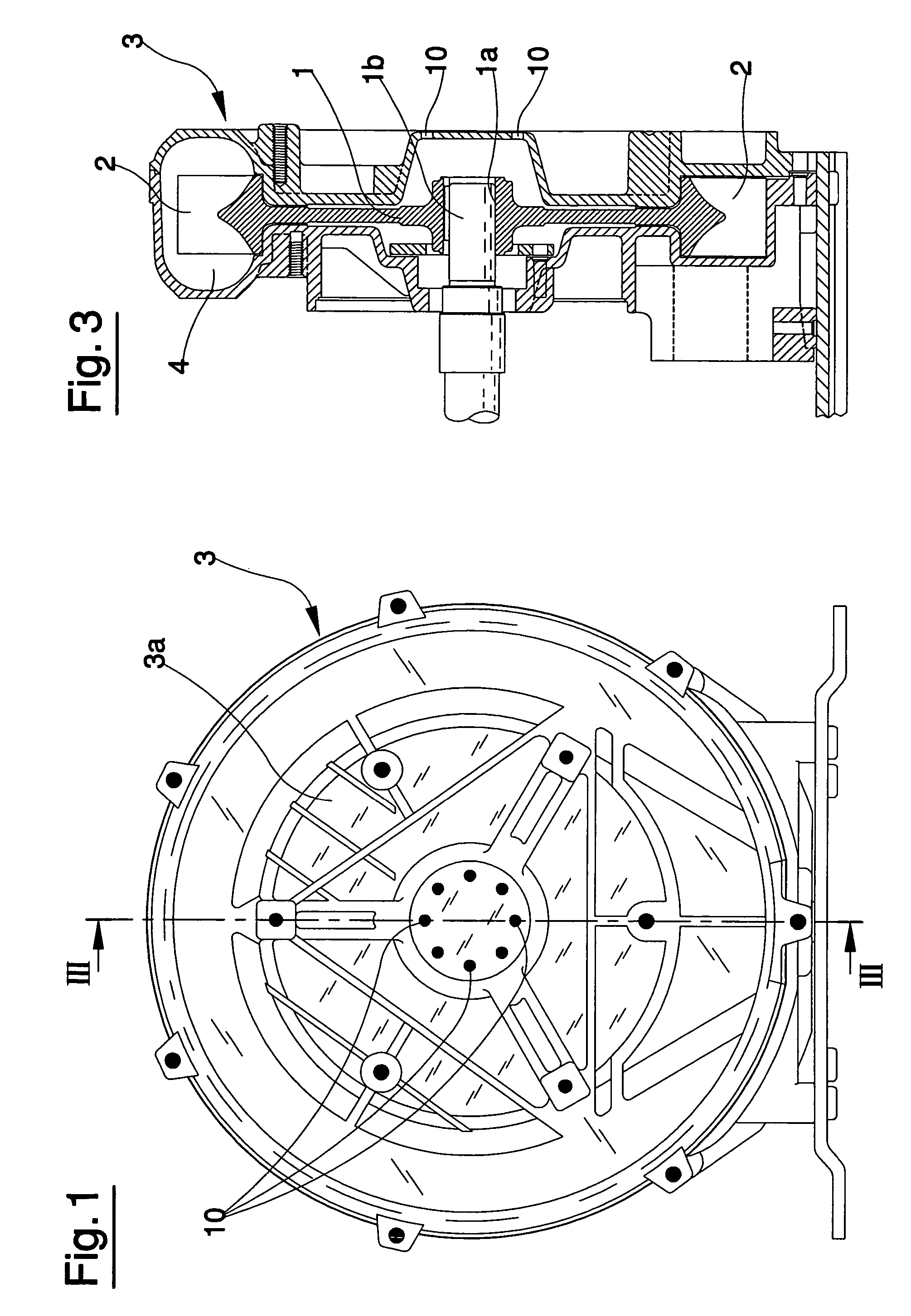
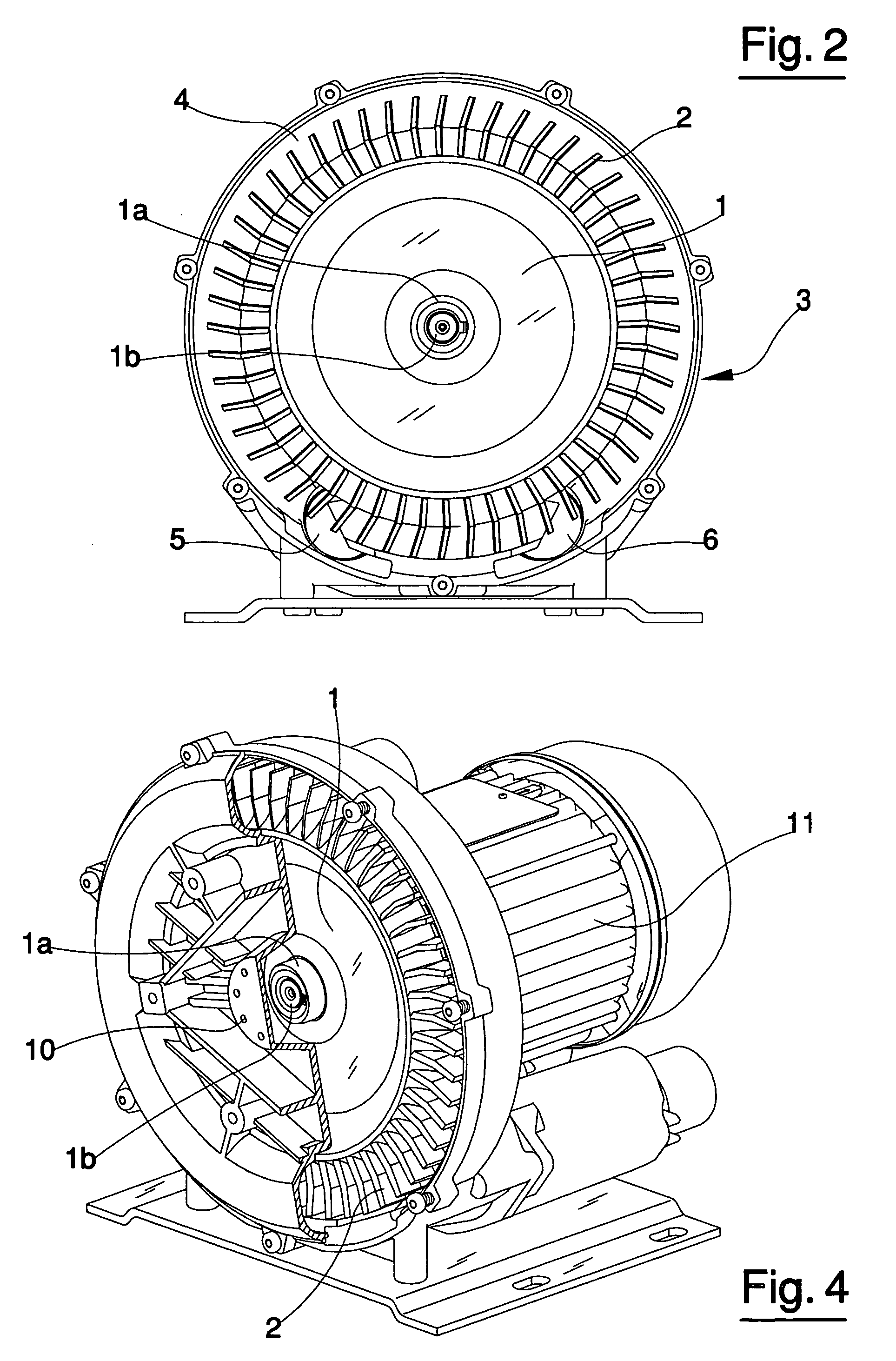
[0018] The machine comprises, as in known machines of this type, an impeller 1 which is provided with a hub 1a keyed on a shaft 1b which is rotated by a motor of known type, such as for example and electric motor 11; the impeller 1 exhibits a central body on which peripheral blades 2 are set.

[0019] The impeller is closed in a casing 3 which defines a circumferential annular conduit 4 in which the blades 2 of the impeller rotate. The casing is normally made in two parts, one of which is connected to the electric motor and the other of which constitutes a front cover; the structure of the casing is obtained by sealedly fastening the two component parts thereof together. The annular conduit 4 exhibits two openings, respectively an intake mouth 5 for aspirating fluid from outside the machine and a delivery-mouth 6 for enabling exit of the fluid from the machine; by action of the impeller blades, the fluid (normally air) is aspirated by the intake mouth 5 and, after having crossed the a...


PUM


Abstract

The machine comprises an impeller, set in rotation by a motor of known type, provided with blades and closed in a casing which defines a circumferential annular conduit in which the blades turn. The annular conduit exhibits two openings, respectively an induction mouth for aspirating fluid from outside the machine, and a delivery mouth from which the fluid exits from the machine. The machine also comprises a further opening which is neither the induction mouth nor the delivery mouth, afforded on the casing and defining a passage which places an inside of the casing in communication with an outside environment.

Description

BACKGROUND OF THE INVENTION [0001] The invention concerns a machine, having a lateral channel and often termed air-ring blowers, comprising an impeller provided with a central body to which peripheral blades are connected. The impeller is closed in a casing which defines circumferential annular conduit, arranged on the external circumference of the casing, in which the impeller blades rotate. The annular conduit exhibits an intake mouth, through which a fluid is aspirated and enters the machine, and a delivery mouth through which the fluid is expelled from the machine itself. [0002] These machines can function either as vacuum pumps or as compressors. In the first case the induction mouth is connected to the environment where a depression is to be created and the delivery mouth is generally connected to the external atmosphere; while in the second case the induction mouth is generally connected to the external atmosphere and the delivery mouth is connected to the environment where a...

Claims


Application Information

Patent Timeline
Patent Type & Authority Applications(United States)
IPC IPC(8): F04D5/00
CPCF04D29/584F04D23/008F04D17/168
Inventor CATTANI, ENNIO
Owner CATTANI SPA
Why Eureka
Try Eureka