Balance beam spotting apparatus

a spotting apparatus and balance beam technology, applied in the direction of balance beams, sport apparatus, gymnastics, etc., can solve the problems of limited type of spotting apparatus and the inability of gymnasts to travel along the length of the balance beam, and achieve the effect of convenient portability

Inactive Publication Date: 2006-11-30
LETTELLEIR MARTIN A
View PDF6 Cites 5 Cited by
  • Summary
  • Abstract
  • Description
  • Claims
  • Application Information

AI Technical Summary

Benefits of technology

[0007] It is one object of the present invention to provide a beam spotting apparatus which can be used by the gymnast without the assistance of another person.
[0008] It is another object of the present invention to provide a beam spotting apparatus that permits the gymnast to travel the length of the beam while using the apparatus.
[0009] It is yet another object of the present invention to provide a beam spotting apparatus that is readily portable and can be used in virtually any desired location.
[0010] To those ends, a portable beam spotting apparatus is provided which comprises a rigid frame having rectangular lower frame portion adapted to be supported upon the floor, a correspondingly sized and configured rectangular upper frame portion supported above and parallel to the lower frame portion by legs attached at either end to corresponding corners of the lower and upper frame portions and a support assembly operable within the frame. The length of each frame portion is slightly longer than the length of a standard balance beam. The support assembly includes cables that extend from the top of one leg to the top of the other leg on each side of the frame and suspension means operable along the cables. Means are provided for tensioning the cables to maintain an appropriate tension in each cable. The suspension means includes a pulley that operates on each cable along the length of the cable and a spotting strap that is suspended from one end from each of the pulleys. The other end of each spotting strap is attached to a swivel on either side of the spotting belt. The length of the spotting straps is adjustable to accommodate the height of the gymnast. The swivel permits the gymnast to perform flips while using the spotting belt without binding or twisting the spotting straps. In use, the balance beam is placed within the frame such that the balance beam extends centrally along the length of the frame, beneath and parallel to the tensioning cables. As the gymnast moves along the length of the balance beam while practicing routines, the pulleys (and thus the entire suspension means) move along the cables with the gymnast. Because the length of the spotting straps is fixed, there is no need for another person to assist the gymnast by manipulating the ropes and pulleys, as is the case in the prior art devices. Should the gymnast slip off the balance beam, she will be prevented from falling to the floor by the support assembly.

Problems solved by technology

The drawback with this type of apparatus is that it does not permit the gymnast to travel along the length of the balance beam since the I-beam is stationary.
While an improvement on the first type of apparatus, this type of spotting apparatus is limited in that it is fixed to the roof of a gym and can only be used where it is so fixed.

Method used


Image

  • Balance beam spotting apparatus
  • Balance beam spotting apparatus
  • Balance beam spotting apparatus

Examples


Embodiment Construction

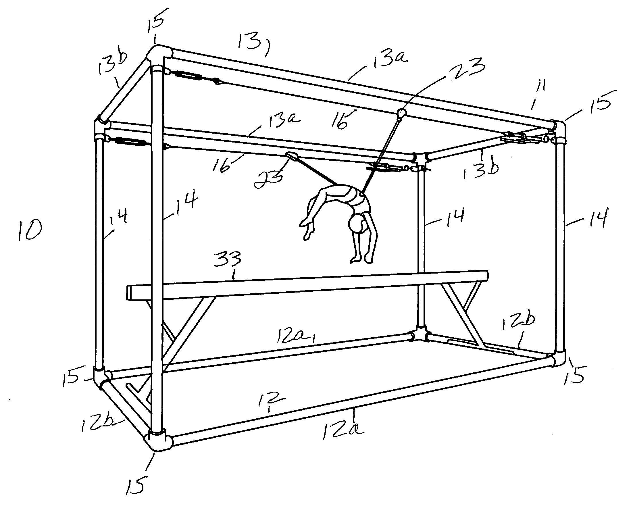
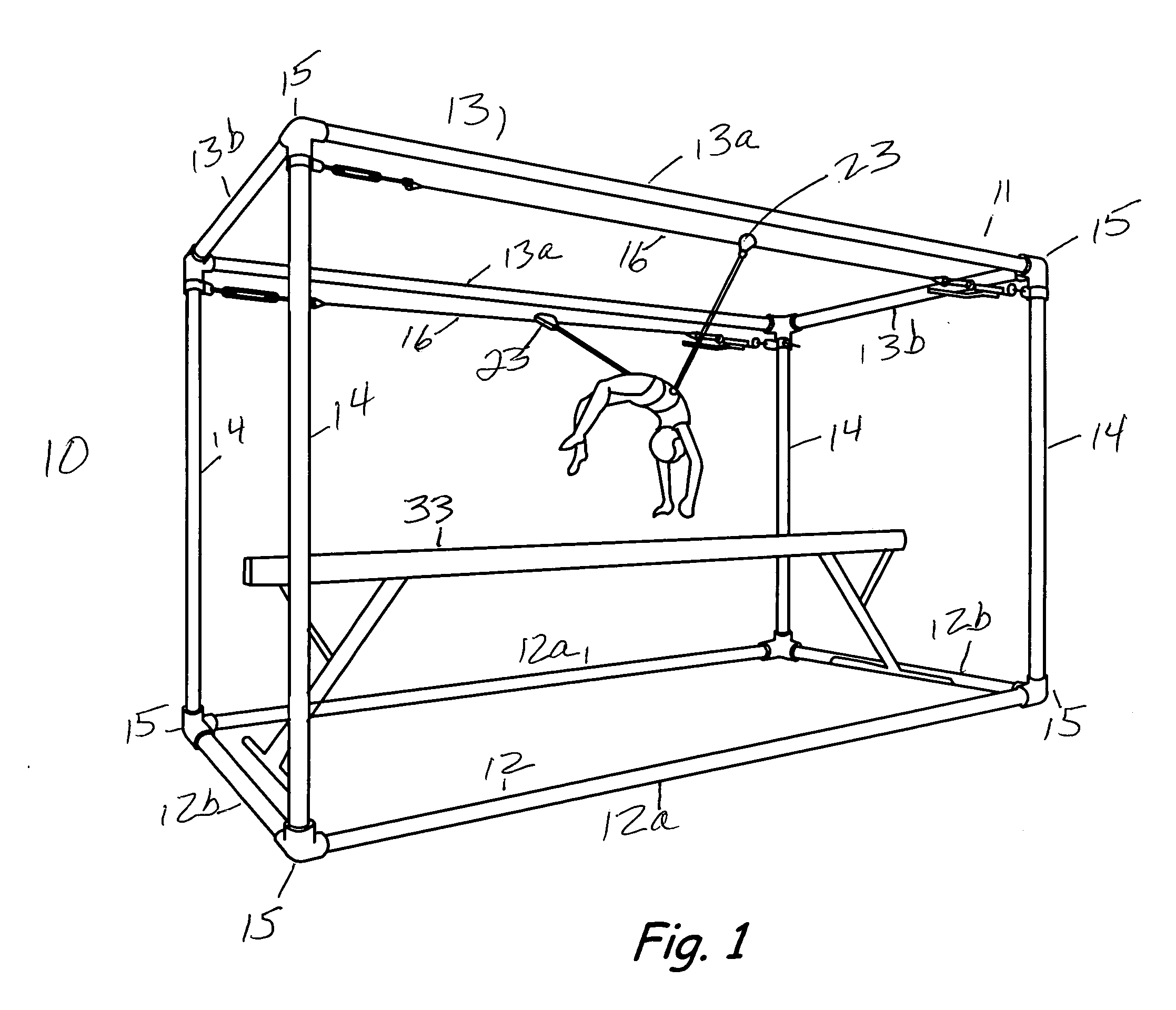
[0015] Referring to the drawing, wherein like numerals represent like elements throughout the several views, there is shown a balance beam spotting apparatus generally designated by the numeral 10. Apparatus 10 comprises a rigid frame 11 having a rectangular lower frame portion 12 with spaced, parallel first members 12a and spaced, parallel second members 12b, and a rectangular upper frame portion 13 with spaced, parallel first members 13a and spaced, parallel second members 13b. Upper frame portion 13 is supported above lower frame portion 12 by legs 14 attached between the comers of lower frame portion 12 and upper frame portion 13. The members 12a, 12b, 13a and 13b and legs 14 are preferably made of tubular aluminum having a circular cross section. This gives the frame 11 strength without weight, thereby facilitating the movement of the frame 11 from one location to another without disassembly.

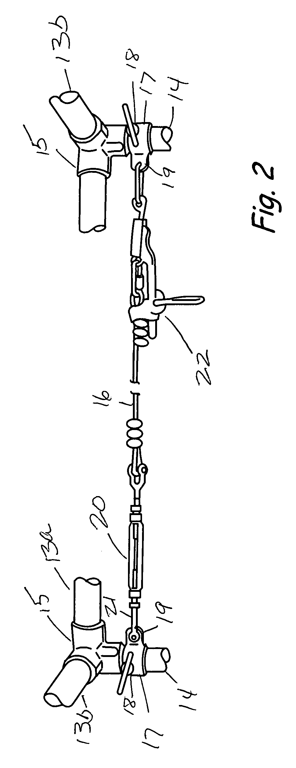
[0016] As best seen in FIGS. 1 and 2, the legs 14 are attached to each corresponding c...


PUM


Abstract

A portable apparatus is provided for “spotting” a gymnast while performing routines on a balance beam. The balance beam spotting apparatus comprises a rigid frame having a lower frame portion adapted to be supported upon the floor, a correspondingly sized and configured upper frame portion supported above and parallel to the lower frame portion by legs attached at either end to corresponding comers of the lower and upper frame portions and a support assembly operable within the frame. The length of each frame portion is slightly longer than the length of a standard balance beam such that the frame may be positioned around a balance beam. The support assembly includes cables that extend from the top of one leg to the top of the other leg on each side of the frame. Means are provided for tensioning the cables to maintain an appropriate tension in each cable. A pulley operates on each cable along the length of the cable. A spotting strap is suspended by one end from each of the pulleys. The other end of each spotting strap is attached to a swivel on either side of the spotting belt worn by the gymnast. The length of the spotting straps is adjustable to accommodate the height of the gymnast. The swivel permits the gymnast to perform flips and other movements while using the spotting belt without binding or twisting the spotting straps. In use, the balance beam is placed within the frame such that the balance beam extends centrally along the length of the frame, beneath and parallel to the tensioning cables. Thus, the gymnast is able to move along the length of the balance beam while practicing routines and to practice skills without the physical assistance of a spotter or coach.

Description

BACKGROUND OF THE INVENTION [0001] The present invention relates to a portable apparatus for spotting gymnasts practicing routines on a balance beam. BRIEF SUMMARY OF THE INVENTION [0002] One of the events common to gymnastics competition is the balance beam. The balance beam comprises an elongate beam approximately 4 inches wide positioned approximately 4 feet above and parallel to the floor upon which the gymnast performs gymnastic routines. The balance beam routines generally include jumps and front and back flips. These routines require great skill on the part of the gymnast to land and balance on the narrow beam. The gymnast moves along the length of the beam while performing such routines. [0003] In competition, such routines are performed without a net or other safety means to prevent the gymnast from falling to the floor if she should fall off the beam. While practicing such routines, however, it is common practice to “spot” the gymnast. Spotting generally involves one perso...

Claims


Application Information

Patent Timeline
Patent Type & Authority Applications(United States)
IPC IPC(8): A63B26/00
CPCA63B4/00A63B69/0064A63B26/003
Inventor LETTELLEIR, MARTIN A.
Owner LETTELLEIR MARTIN A
Why Eureka
Try Eureka