Eureka AIR delivers breakthrough ideas for toughest innovation challenges, trusted by R&D personnel around the world.

Method and apparatus for binding user interface objects to application objects

Inactive Publication Date: 2006-11-30
APPLE INC
View PDF5 Cites 20 Cited by
  • Summary
  • Abstract
  • Description
  • Claims
  • Application Information

AI Technical Summary

Benefits of technology

[0026] To bind a definitional element and a back-end state item, a definitional element is selected from the GUI. A back-end state item (e.g., variable, constant or method) is selected from the GUI either from a list of all items or a list of possible items. A default binding is determined between an attribute of the definitional element and the back-end state item. The default binding is displayed in the GUI for viewing by the user. In most cases, the attribute of the definitional element that is bound to the back-end state item can be displayed in the graphic representation of the definitional element. Since more than one attribute of a definitional element can be bound to the back-end state, the attribute that is fundamental to specifying the definitional element is displayed in the GUI. For example, the attribute that contains the value of a string or identifies the variable that stores a text field's input provides information that is fundamental to

Problems solved by technology

Developing software applications to be used on the Internet is difficult and complex.
There is, however, no tool that provides an environment for interactively defining the bindings using a graphical user interface (GUI) and for generating the binding statements.
In the prior art, there is no mechanism for graphically specifying or viewing bindings between a Web page definition and custom logic.

Method used


Image

  • Method and apparatus for binding user interface objects to application objects
  • Method and apparatus for binding user interface objects to application objects
  • Method and apparatus for binding user interface objects to application objects

Examples


Embodiment Construction

[0043] A method and apparatus for binding user interface objects to application objects is described. In the following description, numerous specific details are set forth in order to provide a more thorough description of the present invention. It will be apparent, however, to one skilled in the art, that the present invention may be practiced without these specific details. In other instances, well-known features have not been described in detail so as not to obscure the invention.

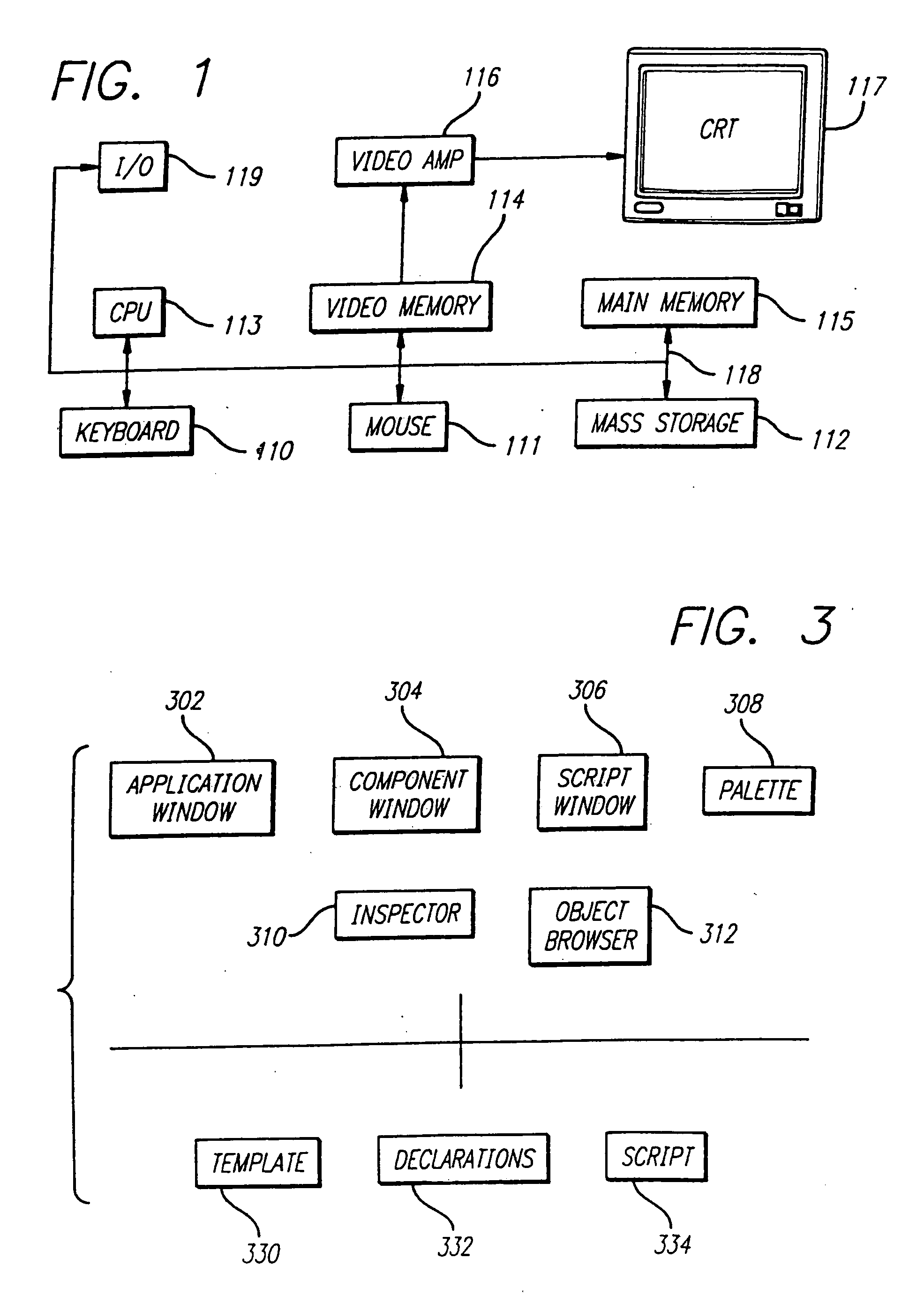
[0044] The present invention can be implemented on a general purpose computer such as illustrated in FIG. 1. A keyboard 110, mouse 111, and I / O 119 are coupled to a bi-directional system bus 118. The keyboard and mouse are for introducing user input to the computer system and communicating that user input to CPU 113. The computer system of FIG. 1 also includes a video memory 114, main memory 115 and mass storage 112, all coupled to bi-directional system bus 118 along with keyboard 110, mouse 111 and CPU...


PUM


Abstract

A graphical user interface (GUI) and accompanying functionality for binding Web page definitional elements to a back-end state (e.g., client- or server-side back-end state) and custom logic is provided. In one embodiment, a template containing definitional elements, custom logic, and bindings are generated that define all or a portion of a Web page based on input received and functionality provided by the invention.

Description

BACKGROUND OF THE INVENTION [0001] 1. Field of the Invention [0002] This invention relates to binding user interface objects to application objects. [0003] 2. Background Art [0004] Developing software applications to be used on the Internet is difficult and complex. There is a need for tools to make it easier for a software developer to create such applications. The problem in developing Internet applications can be understood by examining the Internet and current tools for creating programs. [0005] The Internet is a worldwide network of interconnected computers. An Internet client accesses a computer on the network via an Internet provider. An Internet provider is an organization that provides a client (e.g., an individual or other organization) with access to the Internet (via analog telephone line or Integrated Services Digital Network line, for example). A client can, for example, download a file from or send an electronic mail message to another computer / client using the Intern...

Claims


Application Information

Patent Timeline
IPC IPC(8): G06F3/00G06F17/00G06F9/44
CPCG06F8/20G06F9/4443G06F8/30G06F9/451
Inventor MARCOS, PAULWEBER, ARNAUDTEVANIAN, AVIEWILLRICH, REBECCA EADESHERZER, STEFANIEFEDERIGHI, CRAIG
Owner APPLE INC
Why Eureka
Eureka Blog
Learn More