Free end band and seal

a free end and seal technology, applied in the direction of hose connections, screws, applications, etc., can solve the problems of inelastically deformed bands, increased installation difficulty or complexity, and extreme environmental conditions in outdoor installations, so as to prevent waste of materials, reduce labor costs, and high strength

Active Publication Date: 2006-12-07
BAND IT IDEX
View PDF8 Cites 7 Cited by
  • Summary
  • Abstract
  • Description
  • Claims
  • Application Information

AI Technical Summary

Benefits of technology

[0010] The needs described in the preceding paragraphs have existed for a long time without solution or resolution. The present invention satisfies this long-felt need. The present invention relates to a high strength, pre-cut free end band and seal, generally comprising a pre-cut band of a predetermined length having a first free end and a pre-formed second end that forms a substantially closed loop of band material and a seal captured within the loop of band material that, when subjected to a clamping force, create a finished band clamp that restrains or secures one or more objects. Preforming the band and providing bands at predetermined lengths prevents wasted material and reduces labor costs. The pre-formed loop of band material is preferably spring-loaded to retain a seal within the loop of material so that a seal may be preassembled with a band for packaging, shipping and use in the field, as a complete unit. The loop is also elastic to the extent the seal may be manually removed without permanent change to the preformed loop. The loop of band material may further include a capture element to inhibit accidental or unintended removal or disassembly of the seal from the band. Capture of the band and seal facilitates efficiency in the field by eliminating the need for the field worker to assemble bands and seals in the field. It further promotes preassembly because the probability of dislodging the preassembled seal during shipment and installation is reduced. Releasably capturing a seal in an elastic rather than inelastic way, such that the seal cannot be accidentally dislodged from the band, but can be manually removed from the band, reduces frustration on the part of the installers, reduces installation time, reduces potential environmental problems and reduces wasted material.
[0011] In more than one embodiment of the present invention, the pre-formed second end of the band also positively positions the seal relative to the band to facilitate insertion of the free end of the band into the seal and to facilitate the action of the crimping tool to engage and deform the seal and overlapping band material. Positively positioning the seal relative to the band for optimized engagement by a power crimping tool also saves time and provides a more consistent clamped band. Each of these advantages facilitates end use application in the field where circumstances and environmental conditions may be challenging and adverse.

Problems solved by technology

Although the buckle may be removed, the band must be inelastically deformed to do so.
However, outdoor installations can involve extreme environmental conditions.
In addition, the location may add further difficulty or complexity to the installation, such as ocean-based oil drilling platforms and pipe laying barges.
All of these factors, and others, can make installation difficult.
Because of environmental and / or location-specific difficulties or complexities, dropping a seal creates frustration for the installer, increases installation time and adds to increased costs.
The cost associated with the banding operation is further increased if the seal is lost and creates environmental problems if the seal is lost in the ocean.
Indeed, when assembling the band and seals on location, seals are dropped, or are assembled onto the band in an upside down orientation, with the seam formed by the overlapping legs of the seal forcing outwardly, which results in a weaker clamp.
However, additional handling of the band and seal increases the likelihood that the seal will be dropped or dislodged from the band.
Cutting custom lengths of band on location also results in wasted materials, potential environmental problems, health risks from the sharp edges of cut banding material and increased labor time.
This can create health risks for the installer and others who have to work around and in the vicinity of the cut band.
The excess length may be greater than necessary to accomplish the banding task and, therefore, results in waste.
The excess piece of material may also be dropped and need to be retrieved, or lost in the ocean.
However, from the installer's perspective, this is preferable to cutting a length of band that is too short and having to cut a second length of band to complete the job, resulting in the discarded first band which was too short and the excess length cut from the second band.
Even if the seal is not assembled correctly and is not dropped from the band, actual installation also can be problematic.
However, little space may exist between the seal and the preformed band portion 18 for inserting the free end 20, and the rough or unevenly cut leading edge 20 of the band may not easily fit in the available space or may actually prevent or seriously inhibit insertion.
In addition, depending upon the installation site, there may also be difficulties in positioning the crimping tool relative to the seal and overlapping band portions, which can lead to an improperly crimped seal.
Avoiding the bent portion 18 may be difficult given the close proximity of the bent portion 18 of the band to the seal during crimping.
As can be imagined, these problems can be exacerbated in adverse environments and in awkward installation locations.
Unfortunately, the seals are not truly captured.
As a result, many of the preassembled band and seal combinations become entangled or are further bent in unintended ways under the weight of the other bands and seals in the shipping container, causing the seals to become dislodged during transport or as the intertwined bands are removed from the container.
Moreover, as the assembled bands and seals are removed from a container and are otherwise handled as part of shipping and installation, the bent end 18 may become unbent and the seal is susceptible to falling off either end of the band.
Therefore, little advantage is achieved in preforming or pre-assembling the bands in this manner.

Method used


Image

  • Free end band and seal
  • Free end band and seal
  • Free end band and seal

Examples


Embodiment Construction

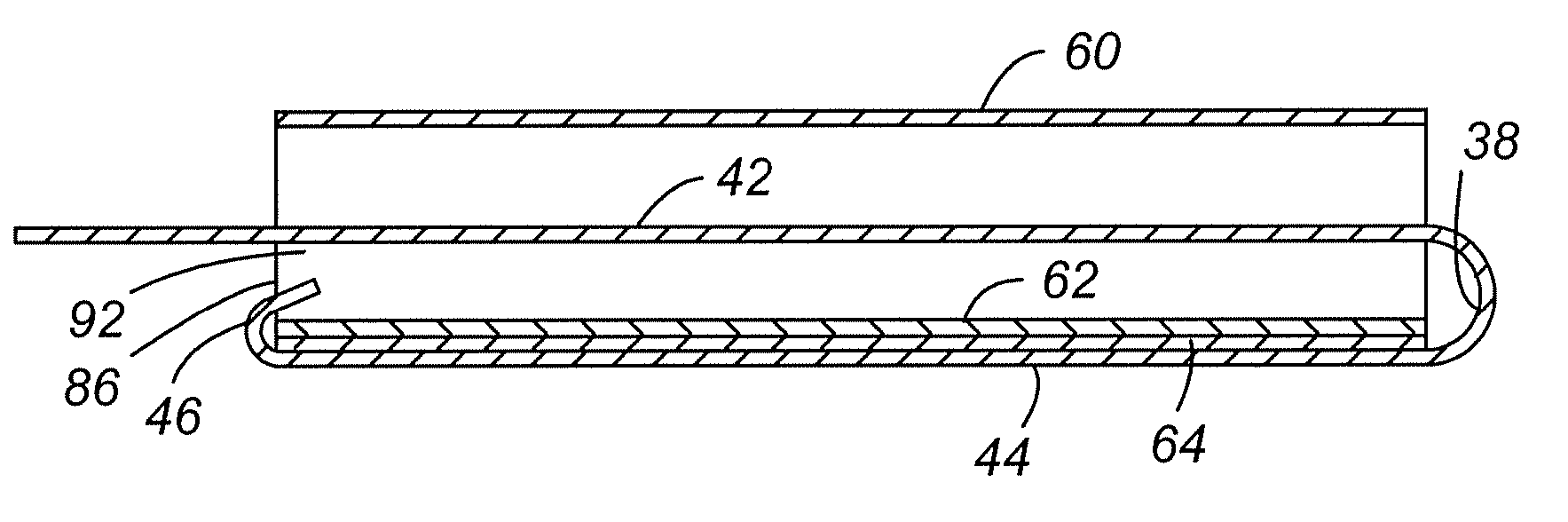
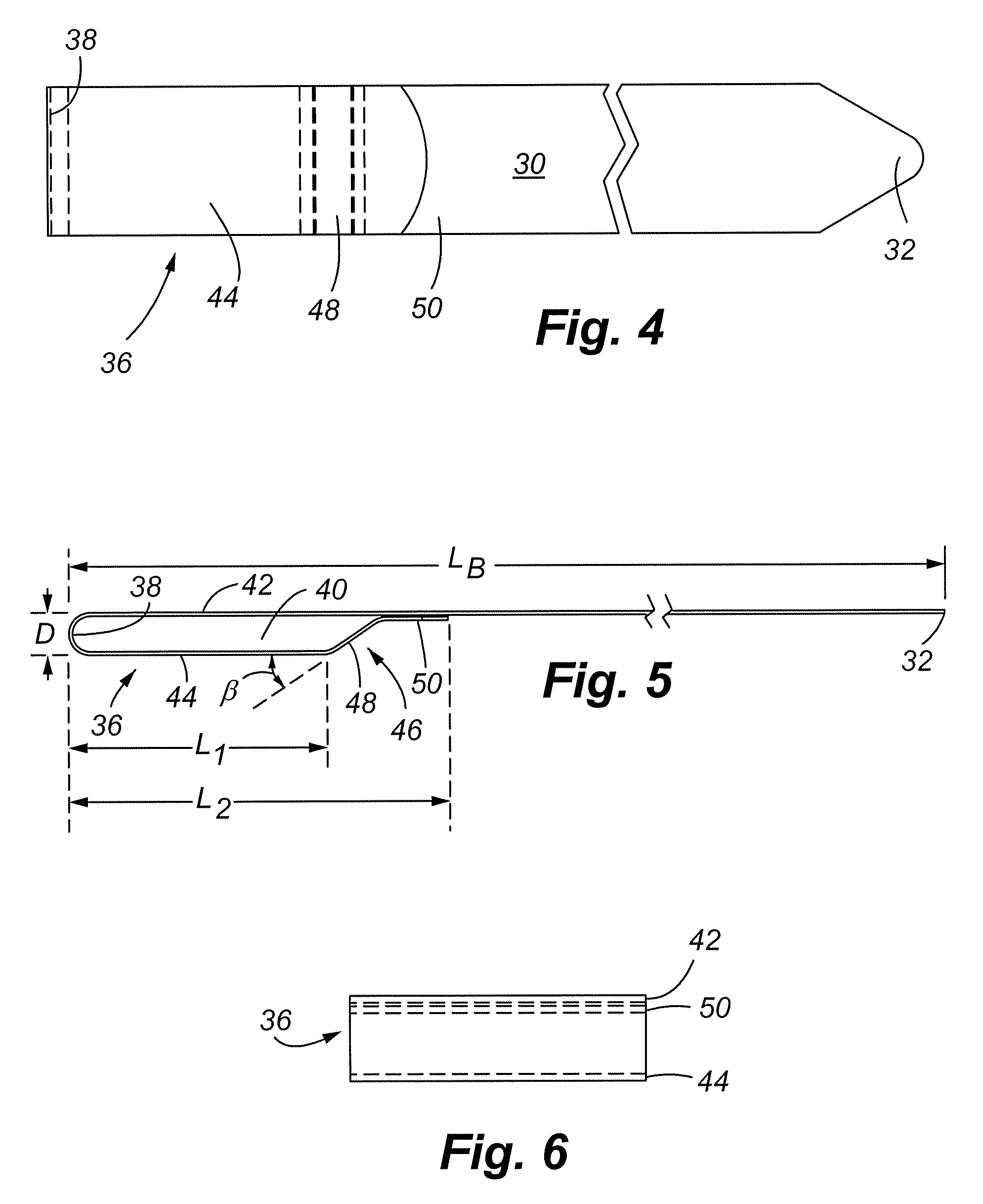
[0050] A preformed band 30 of one embodiment of the present invention is shown in FIGS. 4-6. The illustrated band shown is 1.25 inches wide, although depending upon the application, it may be narrower or wider. For example, it may be 0.75 inches wide or 1.5 inches wide. The band is approximately 0.030 inches thick, although depending upon the application it may be thinner or thicker. An acceptable range of band thickness is approximately 0.010 to 0.044 inches, and is preferably 0.030. A seal is shown in FIGS. 7-10B. Preferably, the band and seal are made of stainless steel or other materials capable of withstanding not only the tensile forces applied to the band to secure or restrain banded objects, but to also withstand a large range of environmental conditions. Examples of suitable materials include Inconel® 625, Monel® 400, and Incoloy® 27-7SMO made by Huntington Alloys Corporation and AL-6XN made by Allegheny Technologies, Inc.

[0051] As shown in FIG. 5, the length of the band 3...


PUM


Abstract

A pre-cut and preformed free end band and seal of a predetermined length, and method of making and using the same is disclosed. The band is preformed with a substantially closed loop of band material to capture a seal to provide a preassembled band and seal wherein the seal is generally inhibited from being dislodged during packing, shipment, handling and installation. The band and seal are also formed in a manner to facilitate relative positioning of the band and seal as well as placement of a crimping tool relative to the band and seal for optimized crimping of the band and seal.

Description

CROSS REFERENCE TO RELATED APPLICATION [0001] The present application claims the benefit, under 35 U.S.C. § 119(e), of U.S. Provisional Patent Application Ser. No. 60 / 688,485 filed Jun. 7, 2005, entitled “Free End Tie and Clamp,” the entire content of which is incorporated herein reference in its entirety.FIELD OF THE INVENTION [0002] The present invention relates to banding and restraining large objects, in many instances where the objects are difficult to access and where the objects are exposed to extreme environmental conditions. More particularly, the invention relates to a method of making an improved preformed band with a band formed with a captured seal, the resulting band and seal combination, and the method of using the same. BACKGROUND OF THE INVENTION [0003] Band clamps come in a variety of shapes and sizes and are used to secure or restrain one or more objects, also of varying size depending upon the application. In some applications, the bands are relatively small, for...

Claims


Application Information

Patent Timeline
Patent Type & Authority Applications(United States)
IPC IPC(8): B65D63/02
CPCB65D63/06Y10T24/49Y10T24/1465Y10T24/1457
Inventor INGALLS, DOUGLAS J.TRAN, BAI KIETGRANT, DANSWETLIC, BRIANMOSSBRUCKER, MARKNELSON, DANIEL J.LEIST, RENE
Owner BAND IT IDEX
Why Eureka
Try Eureka