
Clothes dryer sensor compensation system and method

a technology of compensation system and clothing dryer, which is applied in the direction of dryers, drying machines with progressive movements, lighting and heating apparatus, etc., can solve the problems of high variability of the voltage signal of the moisture sensor, inability to accurately reflect the true moisture content of clothes, and inability to accurately reflect the moisture content of samples, etc., to achieve the effect of reducing the noise contained

Inactive Publication Date: 2006-12-07
MABE CANADA
View PDF5 Cites 14 Cited by
  • Summary
  • Abstract
  • Description
  • Claims
  • Application Information

AI Technical Summary

Benefits of technology

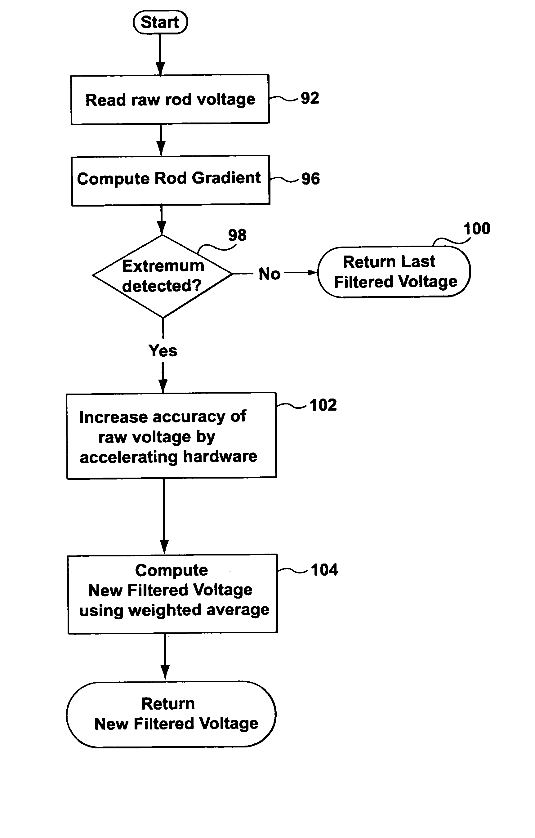
[0011] The appliance of the present invention may further include a noise-reduction filter coupled to the signal acceleration processor to receive the predicted moisture signal values from the signal acceleration processor and reduce the noise contained therein. This filtering may take many forms and in one embodiment computes a new filtered voltage using a time dependent weighted average of the predicted moisture signal values.

Problems solved by technology

As can be appreciated, the voltage signal from the moisture sensor may be highly variable over time and may not accurately reflect the moisture content of the clothing articles.
The articles may from time to time contact the electrodes of the moisture sensor and sometimes not come into contact with the electrodes due to generally random tumbling patterns of the clothes.
Filtered sampled voltages tend to approximate the moisture level or target voltage level for full loads after the clothing has partially dried; however, during the initial stages of the drying cycle the sampled voltages may not accurately reflect the true moisture content of the clothes due to sensor response time.
When the sensor response time is relatively long as compared to the length of time clothing contacts the sensor, the filtered sampled voltages tend not to accurately reflect the actual voltage.
This problem is more pronounced for small loads that do not come into contact with the sensor as frequently as large loads.
This makes it difficult for a dryer during an automatic drying cycle to accurately predict the time required to dry the clothing.
Another factor affecting the accuracy of the sensor to detect moisture content occurs when clothing articles are not evenly dried.
That is some portions of the clothing may be wetter than other portions of the clothing and the wetter portions may not be accurately sensed by the circuit for short contact periods due to response time of the sensors.

Method used


Image

  • Clothes dryer sensor compensation system and method
  • Clothes dryer sensor compensation system and method
  • Clothes dryer sensor compensation system and method

Examples


Embodiment Construction

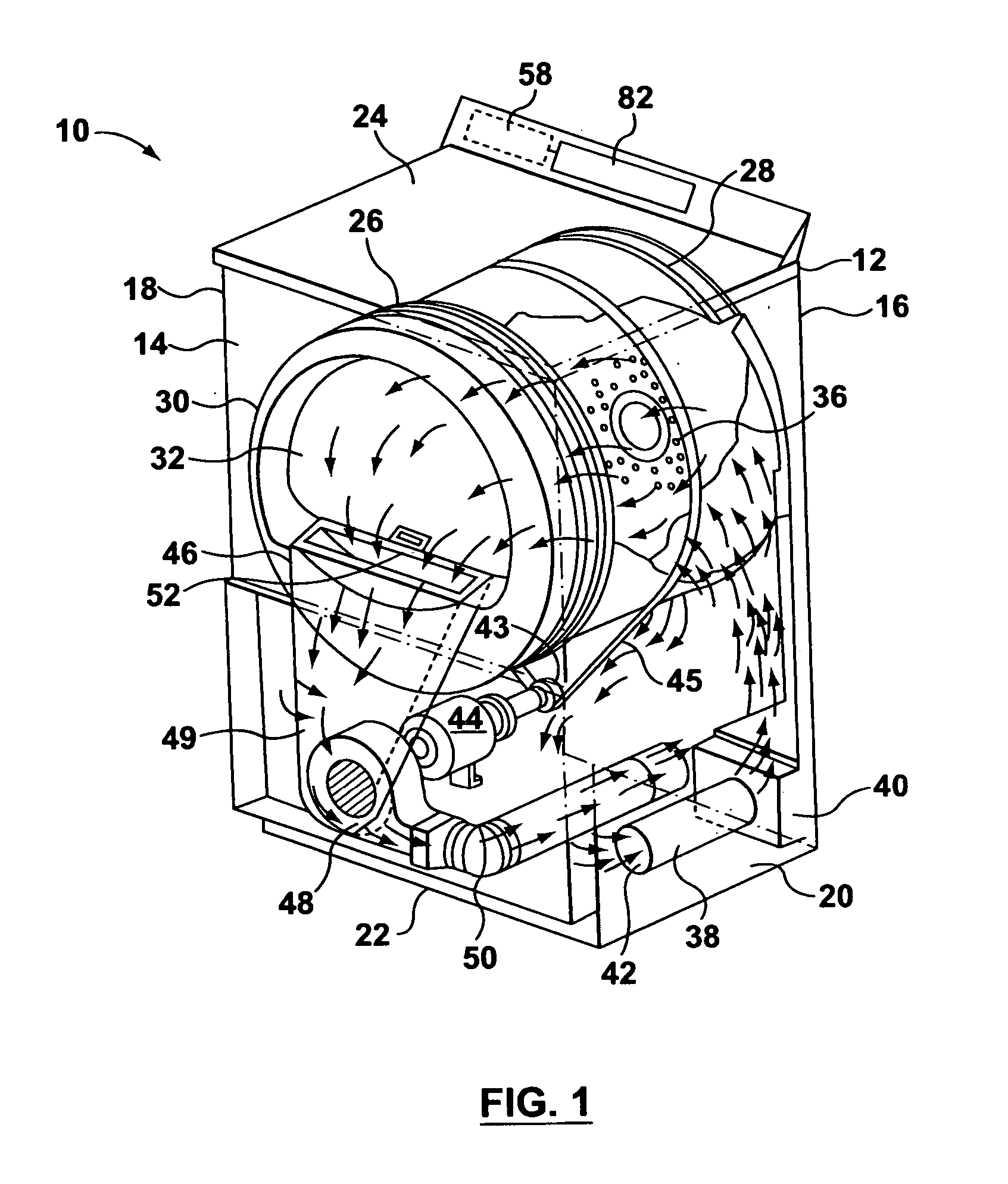
[0029]FIG. 1 shows a perspective view of an exemplary clothes dryer 10 that may benefit from the present invention. The clothes dryer includes a cabinet or a main housing 12 having a front panel 14, a rear panel 16, a pair of side panels 18 and 20 spaced apart from each other by the front and rear panels, a bottom panel 22, and a top cover 24. Within the housing 12 is a drum or container 26 mounted for rotation around a substantially horizontal axis. A motor 44 rotates the drum 26 about the horizontal axis through, for example, a pulley 43 and a belt 45. The drum 26 is generally cylindrical in shape, having an imperforate outer cylindrical rear wall 28 and a front flange or wall 30 defining an opening 32 to the drum. The front wall 30 and opening 32 are normally closed by a door (not shown). Clothing articles and other fabrics are loaded into the drum 26 through the opening 32. A plurality of tumbling ribs or baffles (not shown) are provided within the drum 26 to lift the articles a...


PUM


Abstract

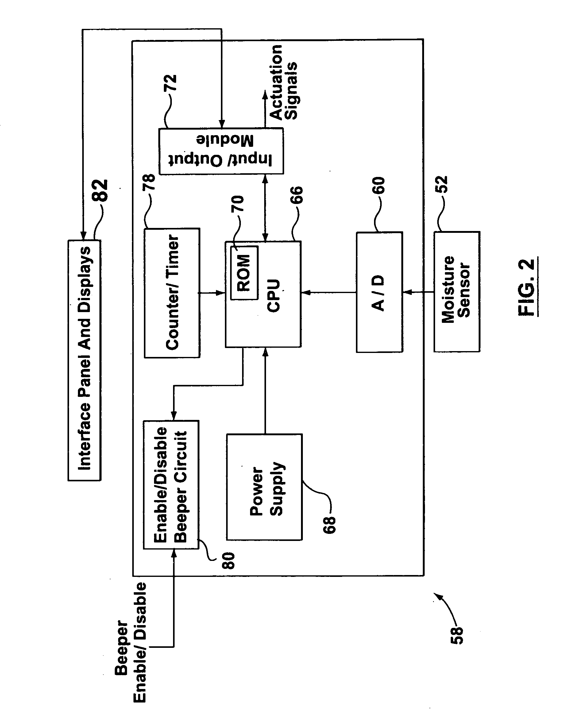
A clothes drying appliance has a moisture sensor and a signal acceleration processor coupled to receive and monitor a moisture signal from the moisture sensor. The processor determines signal gradients in the moisture signal and detects either minimums or maximums in the moisture signal when a sign change occurs between two successive signal gradients. The processor uses the detected local minimum or maximum information and the gradient preceding the detected local minimum or maximum to extrapolate a predicted moisture signal value for the clothing articles. The generation of the predicted moisture signal compensates for sensor response time.

Description

FIELD OF THE INVENTION [0001] The present invention relates to an appliance for drying clothing articles, and, more particularly, to a dryer using microprocessor based controls for controlling dryer operation. BACKGROUND OF THE INVENTION [0002] It is common practice to detect the moisture level of clothes tumbling in a dryer by the use of moisture sensors located in the dryer drum. A voltage signal from the moisture sensor is used to estimate the moisture content of the articles being dried based on the actual characteristics of the load being dried. The sensors are periodically sampled to provide raw voltage values that are then filtered, or smoothed, and inputted to processor modules that determine when the clothes are dry, near dry, or at a target level of moisture content, and the drying cycle should terminate. [0003] As can be appreciated, the voltage signal from the moisture sensor may be highly variable over time and may not accurately reflect the moisture content of the clot...

Claims


Application Information

Patent Timeline
IPC IPC(8): F26B3/00F26B13/10D06F34/04D06F34/08D06F34/18
CPCD06F58/28D06F2103/10D06F34/04D06F34/18D06F34/08D06F2105/28
Inventor PEZIER, NICOLASBEAULAC, SEBASTIEN
Owner MABE CANADA
Learn More