Vacuum eliminator

a vacuum eliminator and vacuum technology, applied in water installations, thin material processing, construction, etc., can solve the problems of not being able to achieve the effect of balancing the safety of returning water operation, avoiding denaturation and failure, and avoiding prior ar

Inactive Publication Date: 2006-12-07
CHUNG CHIU CHIH
View PDF7 Cites 6 Cited by
  • Summary
  • Abstract
  • Description
  • Claims
  • Application Information

AI Technical Summary

Benefits of technology

[0006] The normal-opened-model vacuum eliminator the prevent invention provides, whose larger ring-shaped side exactly reaches the water inlet edge of the non-returning pipe, in which some interlinked vents are designed on the larger ring-shaped side of the pressure controller, and a leakage-proof pad is designed for on the ladder-shaped side for the pressure-resisting ring. In that way, the pressure-resisting ring is pushed towards the pressure controller and the leakage-proof pad exactly would be absorbed by the vacuum at the edge of central hole of the pressure controller in the case of water's access to the non-returning pipe. And the pressure-resisting ring can eliminate the vacuum absorption with its gravity and air suction to form an unobstructed water flow and block backward the water inlet edge of the non-returning pipe to prevent the water flow's reflux from access to the interior of the non-returning pipe to expand the service life of water transport pipeline and balance the returning water operation safety. Thereby, it not only would not easily be involved in denaturation and failure, but also has simple structure and exact operation besides its easy assembly.

Problems solved by technology

Nevertheless, we find out that the forgoing prior art is not so fine as we expected.
Because all its parts are made of plastic materials, they not only would be easily involved in denaturation and failure, but also the outside force is required to block backward the water inlet edge for its small weight while operating themselves.
More seriously, its action would be incorrect.

Method used


Image

  • Vacuum eliminator
  • Vacuum eliminator
  • Vacuum eliminator

Examples


Embodiment Construction

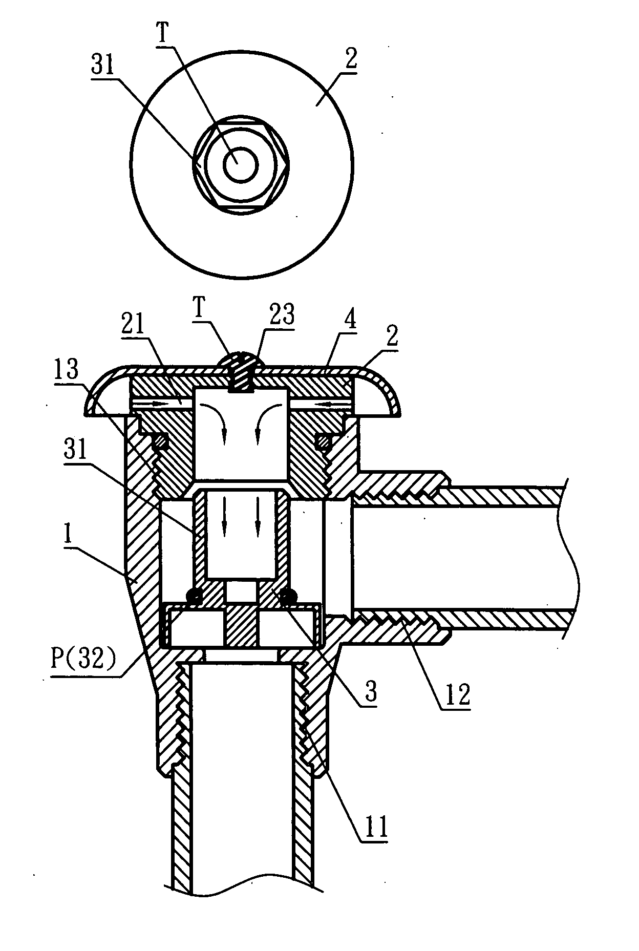
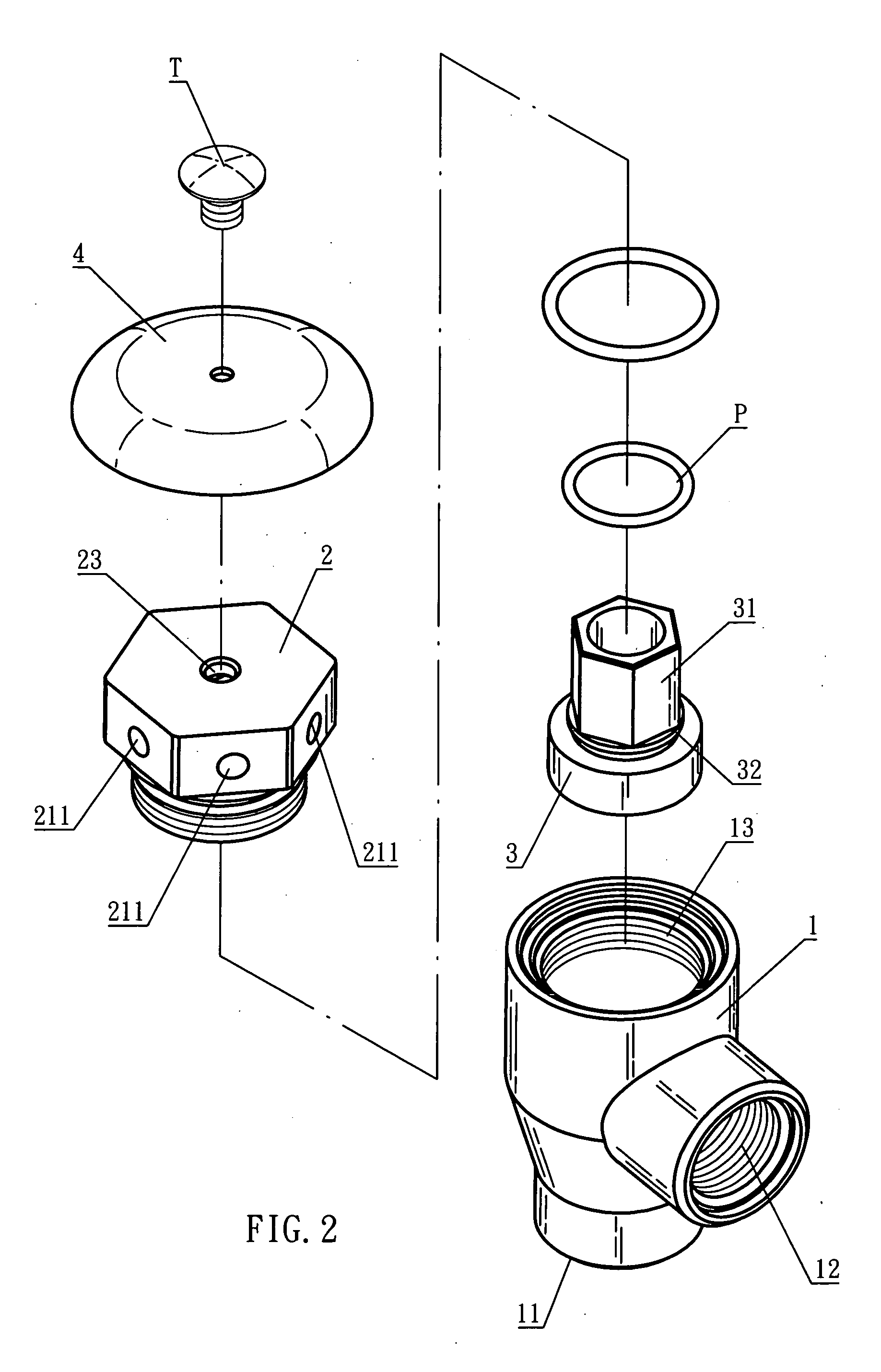
[0013] Referring to the FIG. 2 and FIG. 3, the present invention is to put the screw locking end 31 on the both sides of the water faucet 3 through the shutter S of the granite counter to connect the locking unit 4 and position the water faucet 3 on the shutter S. in which, the locking unit 4 is composed of a locking screw cap 41 for the screw locking end 31, and a packing piece 42 locked in the locking screw cap 41 and a non-returning pad 43, and a water supply pipe 45 whose end and packing piece 41 are fixed and extruded outwards from the lockhole 44. It can prevent the water from seeping by means of tightly jointing with the non-returning pad 43 in the locking screw cap 41 after the locking screw cap is screwed on the screw locking end 31 of the water faucet.

[0014] In addtion, referring to the FIG. 4, the water flow is vertically guided by the water supply pipe to the locking screw cap 41 and lockhole 44, and then to the interior of water faucet 3 through the screw locking end 3...


PUM


Abstract

The prevent invention comprises a non-returning pipe, pressure controller and pressure-resisting ring respectively, whose larger ring-shaped side exactly resists the water inlet edge of the non-returning pipe, in which some interlinked vents are designed on the larger ring-shaped side while a leakage-proof pad on the ladder-shaped side for the pressure-resisting ring. In that way, the pressure-resisting ring is pushed towards the pressure control and the leakage-proof pad exactly would be absorbed by the vacuum at the edge of central hole in the case of water's access to the non-returning pipe. And the pressure-resisting ring can eliminate the vacuum absorption with its gravity and air suction to form an unobstructed water flow and block backward the water inlet edge of the non-returning pipe to prevent the water flow's reflux from access to the interior of the non-returning pipe for longer service life of water transport pipeline and balance the returning water operation safety. Thereby, it not only would not easily be involved in denaturation and failure, but also has simple structure and exact operation besides its easy assembly.

Description

BACKGROUND OF THE INVENTION [0001] 1) Field of the Invention [0002] A kind of normal-opened-model vacuum eliminator, in which some interlinked vents are designed on the larger ring-shaped side of the pressure controller, and a leakage-proof pad is designed on the ladder-shaped side for the pressure-resisting ring. In that way, the pressure-resisting ring is pushed towards the pressure controller and the leakage-proof pad exactly would be absorbed by vacuum at the edge of central hole of the pressure controller in the case of water's access to the non-returning pipe. And the pressure-resisting ring can eliminate the vacuum absorption with its gravity and air suction and block backward the water inlet edge of the non-returning pipe to prevent the water flow's reflux from access to the interior of the non-returning pipe. Thereby, it not only would not easily be involved in denaturation and failure, but also has simple structure and exact operation besides its easy assembly. [0003] 2) D...

Claims


Application Information

Patent Timeline
Patent Type & Authority Applications(United States)
IPC IPC(8): E03C1/10
CPCE03C1/108Y10T137/3331
Inventor CHUNG, CHIU-CHIH
Owner CHUNG CHIU CHIH
Why Eureka
Try Eureka