Hose coupling with a locking mechanism

a locking mechanism and coupling technology, applied in the direction of fluid pressure sealing joints, couplings, pipe elements, etc., can solve the problem that the reduction in the strength mentioned with respect to the configuration of the locking mechanism cannot be accepted in a hitherto used version, and the use of forging technology is too expensive. problems, to achieve the effect of efficient protection against rotation

Inactive Publication Date: 2006-12-07
MAX WIDENMANN ARMATURENFAB
View PDF14 Cites 13 Cited by
  • Summary
  • Abstract
  • Description
  • Claims
  • Application Information

AI Technical Summary

Benefits of technology

[0009] According to the invention, a hose coupling includes two coupling halves which take a coupling end position by relative rotation against each other about a coupling path of no more than 180°. The hose coupling further comprises a locking mechanism that prevents an unintended opening of the coupling. The locking mechanism comprises a latching mechanism, particularly a latching pin mechanism. The latching mechanism is automatically activated in the coupling end position and prevents a relative rotation of the coupling halves against each other. The invention is based on the idea that, contrary to locking pawl mechanisms used hitherto, latching mechanisms can also be realized in large couplings which are produced in a casting process without any weakening of the force transmitting region. The automatically acting latching mechanism offers an efficient protection against rotation for the coupling halves and generally has the advantage that no additional manipulations are necessary for activating the locking mechanism.

Problems solved by technology

Even if the pumping medium is water in most cases, the handling, which is not simple anymore, and the increased potential of danger of large masses under pressure in movable pipes require the arrangement of a locking mechanism.
On the one hand, considering the tools and the number of pieces, the use of forging technology is too expensive.
This is the reason why the couplings are produced in a casting process whereby in turn, the reduction in strength mentioned with respect to the configuration of the locking mechanism cannot be accepted in a hitherto used version.
For this reason, and also due to a plurality of ribs, the coupling state cannot be easily and immediately recognized, and misjudgements of supposed coupled connections cannot be excluded in spite of possible indicators.

Method used


Image

  • Hose coupling with a locking mechanism
  • Hose coupling with a locking mechanism
  • Hose coupling with a locking mechanism

Examples


Embodiment Construction

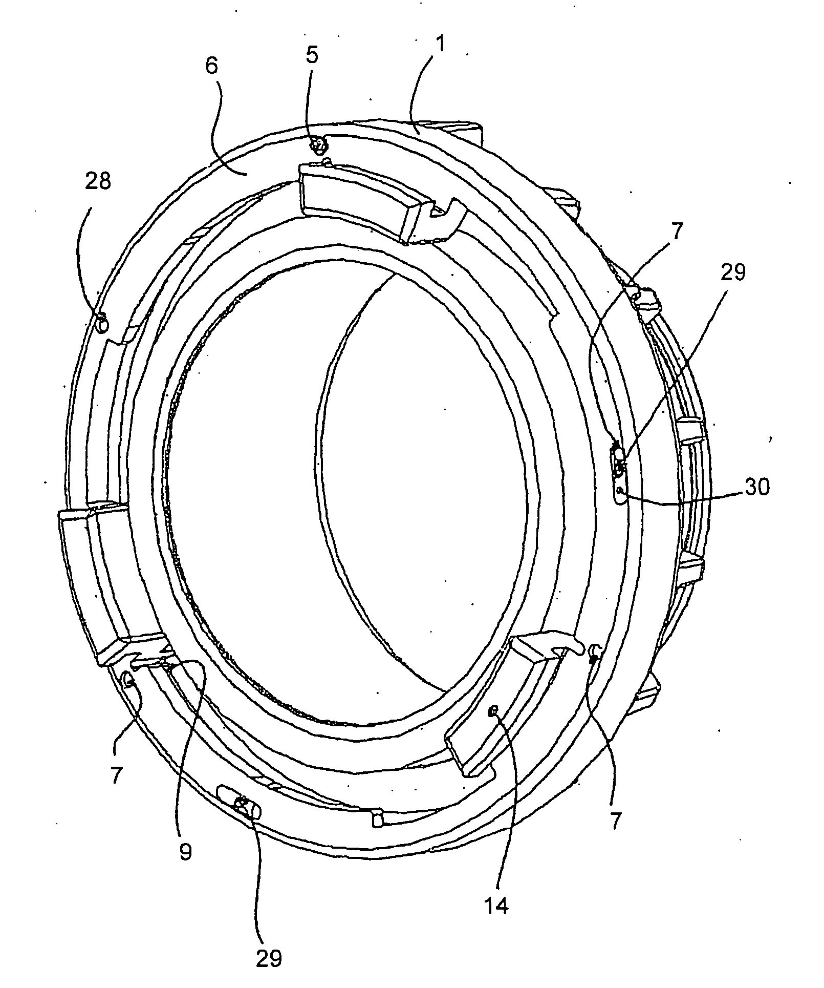
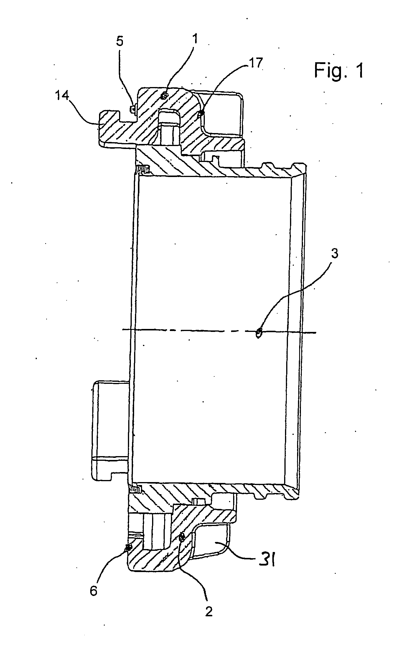
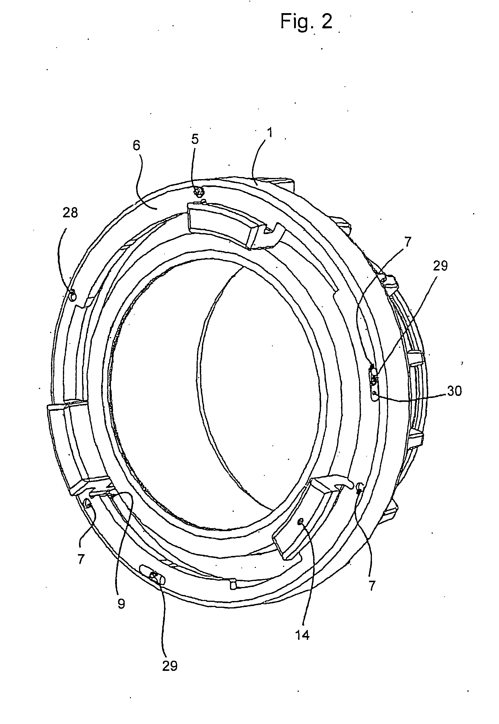
[0020] The Figures show a coupling half of a Storz coupling modified according to the invention and having three cam / shoulder pairs. Since Storz couplings are generally known to a person skilled in the art, only the specific features according to the invention are described in detail in the following description.

[0021] On a collar 1 of a cam piece 2, a latching pin 5 which is mounted in parallel to a flow axis 3, and which is biased by a pressure spring 4, projects a few millimeters beyond an end face 6 facing a counter-coupling half. The latching pin 5 latches, in a coupling end position, into place in a latching hole 7 configured as a blind hole on the counter-coupling half after having run over additional latching points 29. The coupling end position as limitation of the coupling path is realized by a radial face 8 on a stop 9 at an end portion 10 of a coupling shoulder 11.

[0022] The position of the latching pins 5 and of the latching holes 7 is chosen such that they lie one on...


PUM


Abstract

A hose coupling includes two coupling halves which take a coupling end position by relative rotation against each other about a coupling path of no more than 180°. The hose coupling further includes a locking mechanism that prevents an unintended opening of the coupling. The locking mechanism comprises a latching mechanism, in particular a latching pin mechanism. The latching mechanism is automatically activated in the coupling end position and prevents a relative rotation of the coupling halves against each other. The latching mechanism is preferably configured such that, already before reaching the coupling end position, the latching mechanism is activated so far that it counteracts a relative rotation of the coupling halves in an opening direction.

Description

RELATED APPLICATIONS [0001] The application claims priority to German Application No. 20 2005 008 795.5, which was filed on Jun. 6, 2005. BACKGROUND OF THE INVENTION [0002] The invention relates to a hose coupling, in particular to a hose coupling including two coupling halves which take a coupling end position by relative rotation against each other about a coupling path of no more than 180°. [0003] Known “Storz” couplings, which are used in particular in the field of firefighting, belong to an axially closing coupling type. Two identical coupling halves, which each consist of a hose connection and a cam ring rotatably arranged on the hose connection, are characteristic of Storz couplings. In this coupling type, at best only one half can alternatively be configured in one piece in the form of a stationary coupling. [0004] The cam rings of the symmetrical coupling halves can be rotated with respect to the hose connections associated to each half, whereby it is possible to bring the ...

Claims


Application Information

Patent Timeline
Patent Type & Authority Applications(United States)
IPC IPC(8): F16L21/00F16L37/113
CPCF16L37/252F16L37/113
Inventor AMBROSI, JOHANN
Owner MAX WIDENMANN ARMATURENFAB
Why Eureka
Try Eureka