Traffic preemption system signal validation method

a technology of signal validation and traffic preemption system, which is applied in the direction of electrical/magnetic computing, analogue processes for specific applications, instruments, etc., can solve the problems of unauthorized device being used to activate the system, and affecting the operation of the system

Active Publication Date: 2006-12-07
GLOBAL TRAFFIC TECH
View PDF32 Cites 14 Cited by
  • Summary
  • Abstract
  • Description
  • Claims
  • Application Information

AI Technical Summary

Benefits of technology

[0006] The present invention is directed to overcoming the above-mentioned challenges and others that are related to the types of approaches and implementations discussed above and in other applications. The present invention is exemplified in a number of implementations and applications, some of which are summarized below.
[0007] In connection with one embodiment, the present invention is directed to implementations that allow traffic light systems to be remotely controlled using high-integrity data communication. One such implementation employs optical encrypted data being transmitted to traffic light control equipment located at an intersection.
[0008] In a more particular example embodiment, a secure optical-communication traffic-preemption system includes an optical emitter and a traffic light circuit. The optical emitter is adapted to transmit light pulses that represent an encrypted code that is an encryption using a time-varying encryption key including at least an identification code. The traffic light circuit has an optical detector located at a traffic location and adapted to receive the transmitted light pulses, and has a decoding circuit adapted to re

Problems solved by technology

However, due to hearing impairment, air conditioning, audio systems and other distractions, often the driver of a vehicle approaching an intersection will not be aware of a warning being emitted by an approaching emergency vehicle.
This approach can be disadvantageous for certain applications or environments.
For example, one problem with this approach arises when the transmitted data protocol is generally known or can easily be intercepted and re-created by unauthorized users.
Once the transmitted data has been decoded or the transmitted data has been recorded for future playback, an unauthorized

Method used


Image

  • Traffic preemption system signal validation method
  • Traffic preemption system signal validation method
  • Traffic preemption system signal validation method

Examples


Embodiment Construction

[0016] The present invention is believed to be applicable to a variety of different types of validation of operation requests in an optical traffic preemption system. While the present invention is not necessarily limited to such approaches, various aspects of the invention may be appreciated through a discussion of various examples using these and other contexts.

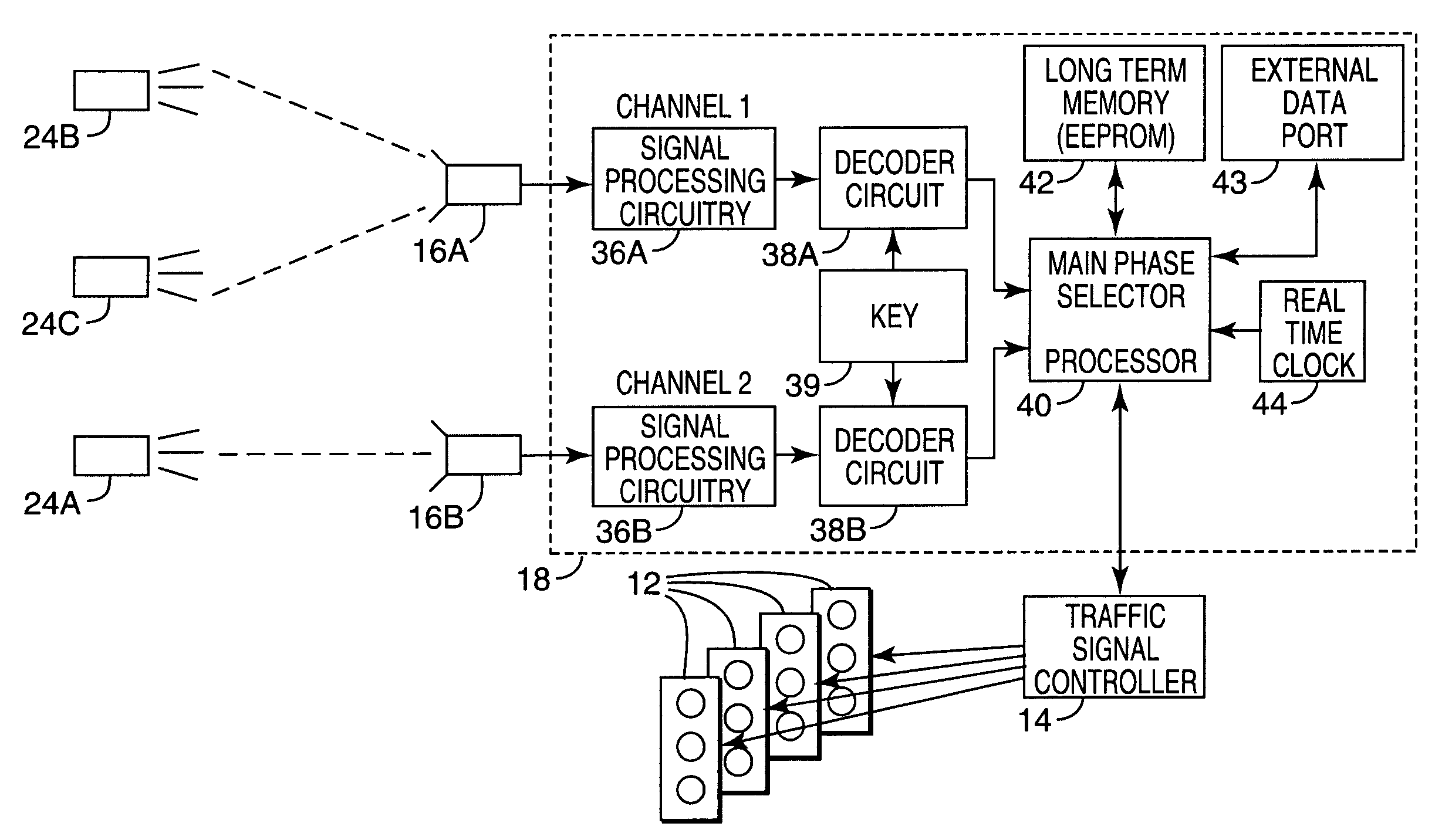
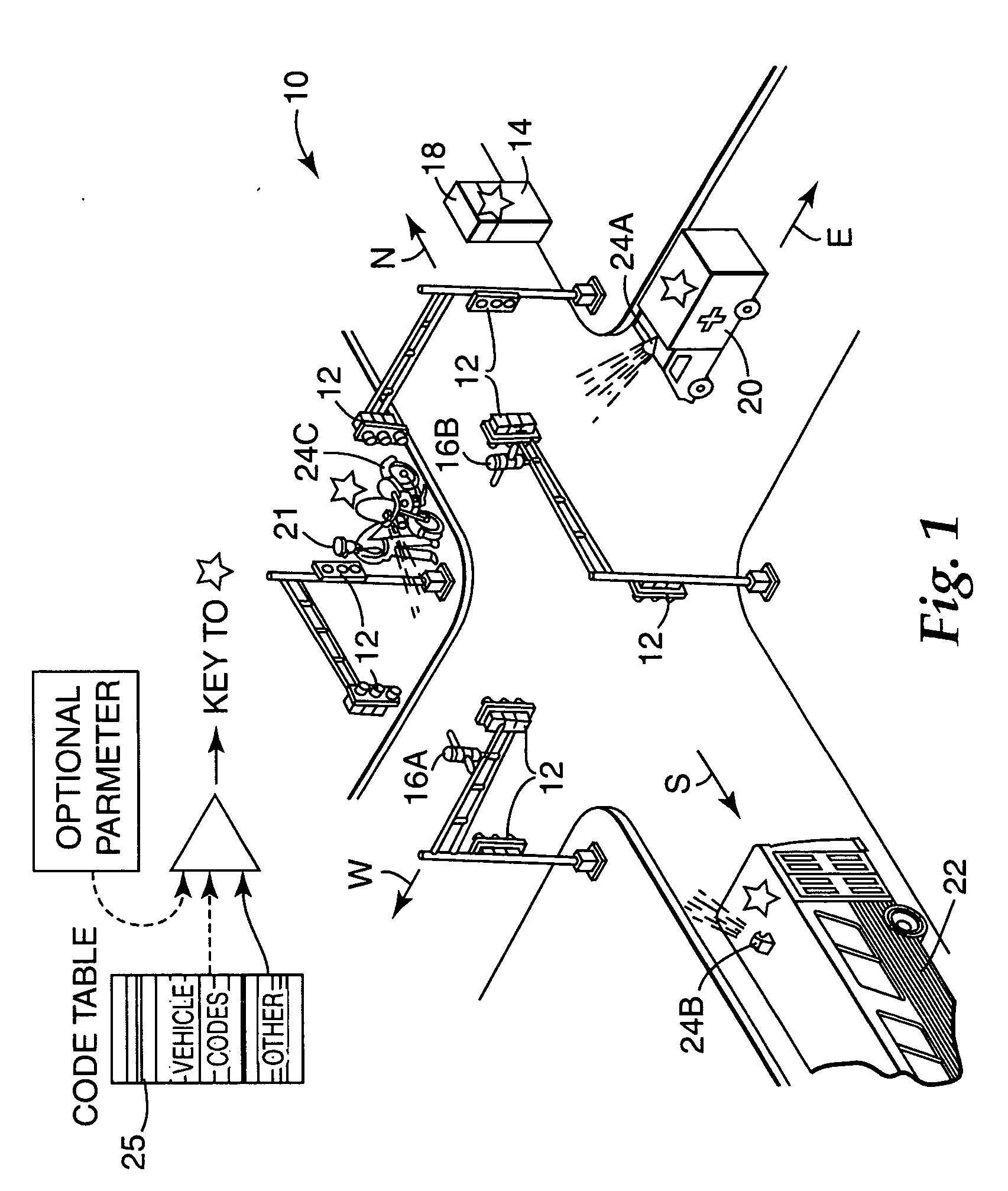
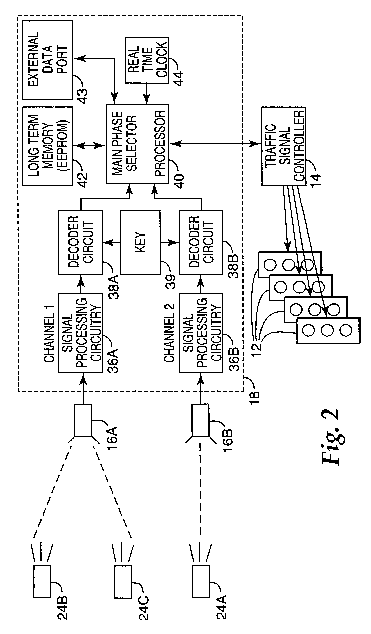
[0017] The optical traffic preemption system shown in FIG. 1 is presented at a general level to show the basic circuitry used to implement example embodiments of the present invention. In this context, FIG. 1 illustrates a typical intersection 10 having traffic lights 12. A traffic signal controller 14 sequences the traffic lights 12 through a sequence of phases that allow traffic to proceed alternately through the intersection 10. The intersection 10 is equipped with an optical traffic preemption system having certain aspects and features enabled in accordance with the present invention to provide secure communication in ...


PUM


Abstract

A secure optical-communication traffic-preemption system and method is provided that securely communicates an identification code from an optical emitter to a traffic location. The optical emitter transmits light pulses that represent an encrypted code that is an encryption using a time-varying encryption key of at least an identification code. An optical detector situated at a traffic location receives the transmitted light pulses. Validation, including decryption using a time-varying decryption key, is attempted for the encrypted identification code represented within the received light pulses. In response to validating the included identification code, a traffic-preemption command is generated for a traffic light at the traffic location.

Description

FIELD OF THE INVENTION [0001] The present invention is generally directed to systems and methods that allow traffic light systems to be remotely controlled using high-integrity data communication, for example, involving optical pulse transmission from an optical emitter to an optical detector that is communicatively-coupled to a traffic light controller at an intersection. BACKGROUND OF THE INVENTION [0002] Traffic signals have long been used to regulate the flow of traffic at intersections. Generally, traffic signals have relied on timers or vehicle sensors to determine when to change the phase of traffic signal lights, thereby signaling alternating directions of traffic to stop, and others to proceed. This situation is commonly exemplified in an emergency-vehicle application. [0003] Emergency vehicles, such as police cars, fire trucks and ambulances, are generally permitted to cross an intersection against a traffic signal. Emergency vehicles have typically depended on horns, sire...

Claims


Application Information

Patent Timeline
IPC IPC(8): G08G1/095
CPCG08G1/087
Inventor SCHWARTZ, MARK A.
Owner GLOBAL TRAFFIC TECH
Why Eureka
Try Eureka