Technique for low grazing angle 3D SAR target recognition

Active Publication Date: 2006-12-07
RAYTHEON CO
View PDF12 Cites 23 Cited by
  • Summary
  • Abstract
  • Description
  • Claims
  • Application Information

AI Technical Summary

Benefits of technology

[0015] The timeline for acquiring a plurality of aspect angles of the target is reduced by using interl

Problems solved by technology

However, sometimes the ground targets of interest are relatively far away, and the radar platform is required to fly at low altitude, forcing the imaging radar to operate at shallow grazing angles.
These long shadows may be insufficient to discern a 3D image of the target with a typical imaging process.
The comple

Method used


Image

  • Technique for low grazing angle 3D SAR target recognition
  • Technique for low grazing angle 3D SAR target recognition
  • Technique for low grazing angle 3D SAR target recognition

Examples


Embodiment Construction

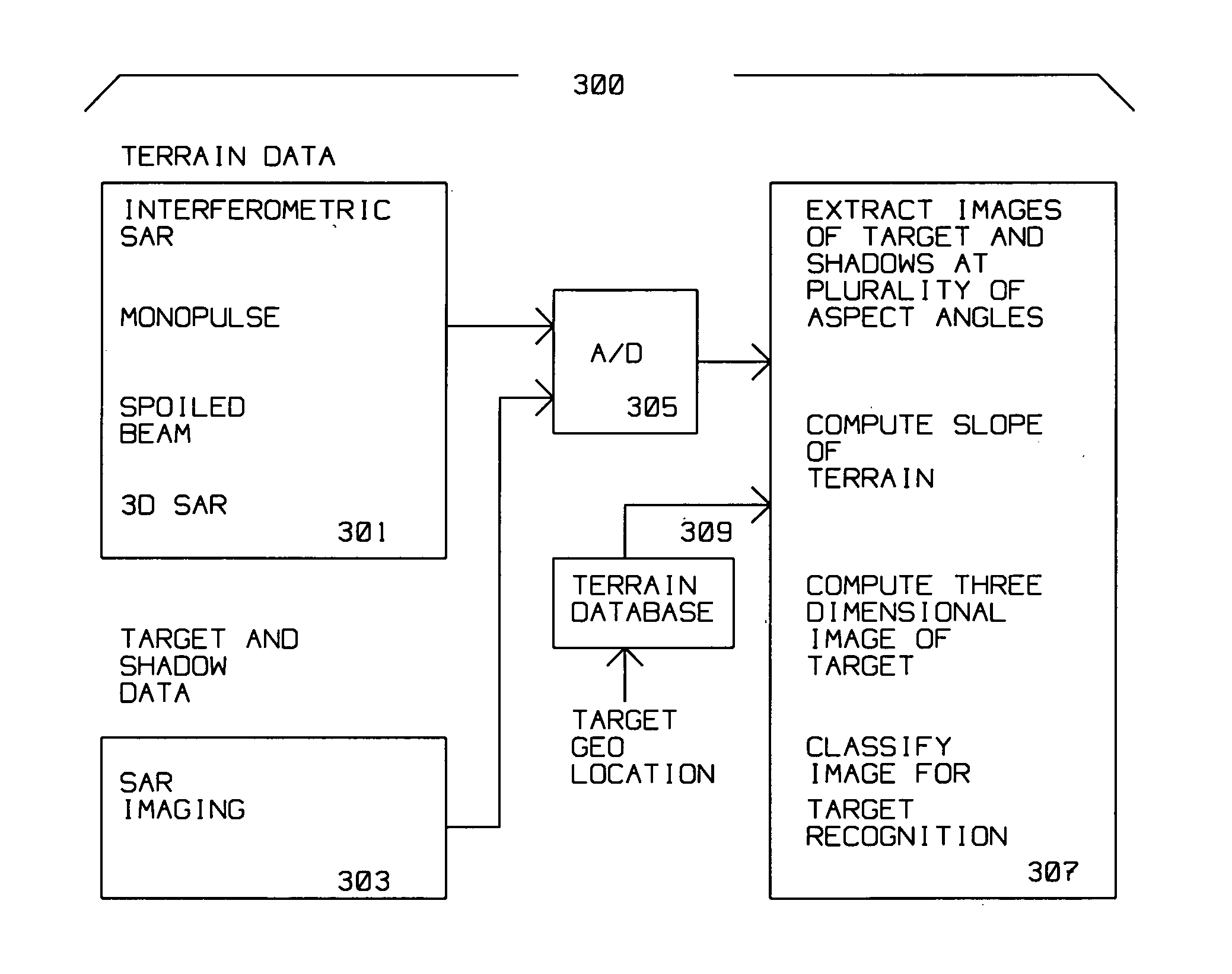
[0020] The present invention avoids above limitations of the prior art by using a radar and method of radar operation for 3 dimensional target recognition from a plurality of SAR images acquired at different aspect angles of the target. The different aspect angles viewed from the radar illuminate the target at low grazing angles for lengthy shadows. The target is identified from the lengthy shadows cast upon uneven terrain, such as a sloping surface. The plurality of images generated while different aspect angles of target are being acquired are combined and processed using Automatic Target Recognition (ATR) methods for target recognition.

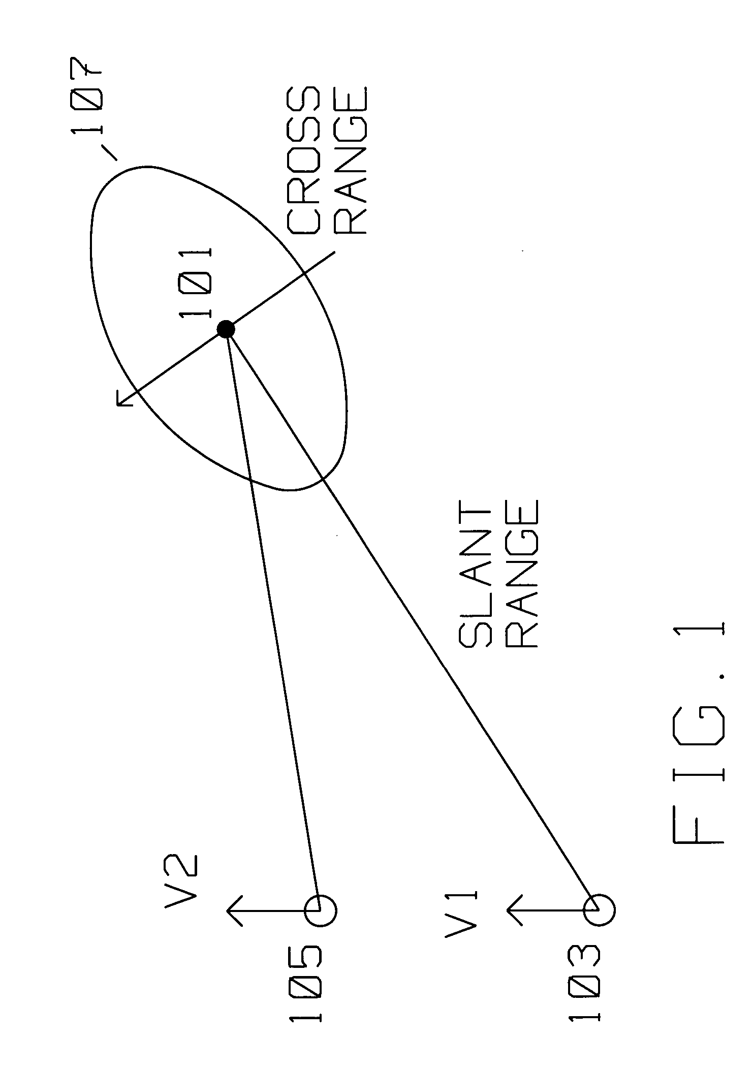
[0021]FIG. 1 shows the typical top view of the geometric relationship between a moving platform carrying a radar transmitter / receiver using Synthetic Aperture (SAR) spotlight methods and target 101 to be imaged by said radar transmitter / receiver. Target 101 is a radar scatterer having an elevation above a ground surface, where the surface may be s...


PUM


Abstract

A radar on a moving platform for three dimensional target recognition of a target on a flat or sloping terrain is described. The target is illuminated from a plurality of locations to generate images at many aspect angles. The radar is positioned at a low grazing angle with respect to the target for generating a shadow of the target on the flat or sloping terrain for each aspect angle of the plurality of aspect angles. The radar comprises an analog to digital converter for converting reflections from the target induced by radar illumination into target digital data and for converting reflections induced by the illumination from the flat or sloping terrain into terrain digital data. The radar further comprises a computer for extracting radar images of the target and its shadow(s) at the plurality of aspect angles at low grazing angles; computing the slope of the terrain from the terrain digital data; correlating a plurality of the radar images to compute a three dimensional image of the target from the shadow of the target upon the flat or sloping terrain; and classifying the three dimensional image for target recognition using a target recognition algorithm.

Description

BACKGROUND OF THE INVENTION [0001] 1. Field of Invention [0002] This invention is in the field of radar imaging at low grazing angles for use with target identification. [0003] 2. Description of the Related Art [0004] Synthetic Aperture Radar (SAR) radar is used for ground mapping as well as target identification. The general principle behind SAR is to coherently combine the amplitude and phase information of radar returns from a plurality of sequentially transmitted pulses from a relatively small antenna on a moving platform. [0005] The plurality of returns creating a SAR image generated by the transmitted pulses along a known path of the platform make up an array. During the array, amplitude as well as phase information returned from each of the pulses, for each of many range bins, is preserved. The SAR image is formed from the coherent combination of the amplitude and phase of return(s) within each range bin, motion compensated for spatial displacement of the moving platform duri...

Claims


Application Information

Patent Timeline
IPC IPC(8): G01S13/90
CPCG01S13/90
Inventor KRIKORIAN, KAPRIEL V.MELLEMA, DWIGHT J.PINES, MICHAEL Y.
Owner RAYTHEON CO
Why Eureka
Try Eureka