Method for driving plasma display panels

a plasma display and plasma technology, applied in the direction of instruments, static indicating devices, etc., can solve the problem of difficult adjustment of driving waveforms, and achieve the effect of effectively driving the pdp

Inactive Publication Date: 2006-12-07
CHUNGHWA PICTURE TUBES LTD
View PDF3 Cites 4 Cited by
  • Summary
  • Abstract
  • Description
  • Claims
  • Application Information

AI Technical Summary

Benefits of technology

[0010] It is therefore an aspect of the present invention to provide a method for driving a plasma displa

Problems solved by technology

However, when the scan electrodes are scanned by the conventional “Dual Scan” scanning method, the driving waveforms are

Method used


Image

  • Method for driving plasma display panels
  • Method for driving plasma display panels
  • Method for driving plasma display panels

Examples


Embodiment Construction

[0024] Reference will now be made in detail to the present preferred embodiments of the invention, examples of which are illustrated in the accompanying drawings. Wherever possible, the same reference numbers are used in the drawings and the description to refer to the same or like parts.

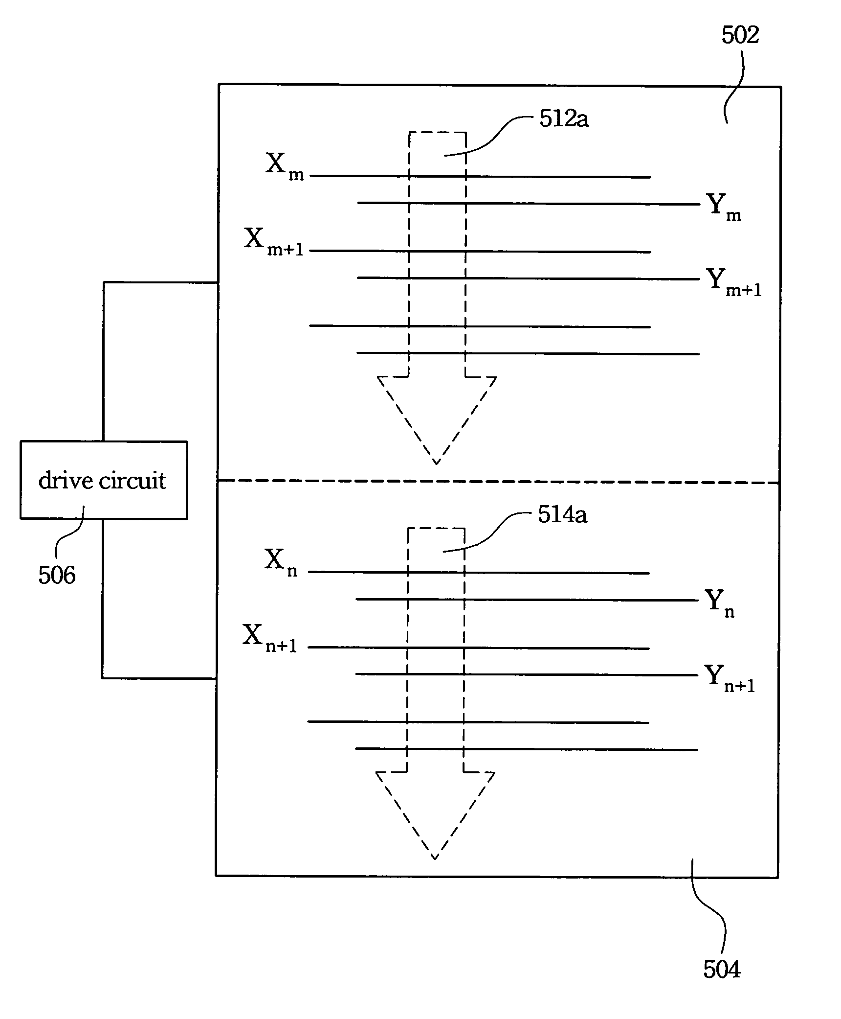
[0025] In order to clearly interpret preferred embodiments of the present invention, the following descriptions firstly explain reasons which cause the large difference between discharging properties of different scanning regions by two examples is having different relative relations between the electrode arrangement sequence and the scanning direction of their own scan electrodes and common electrodes.

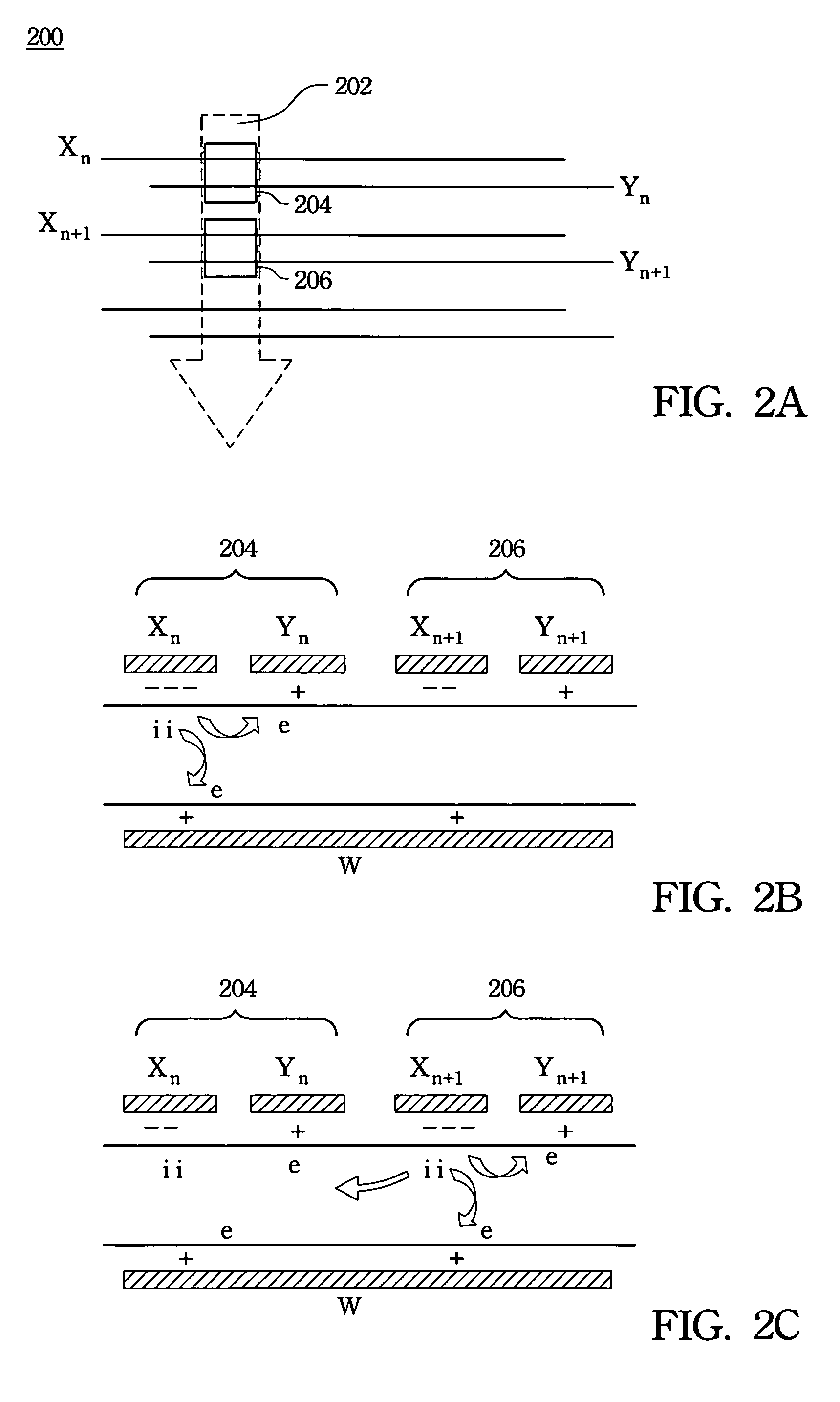
[0026] First of all, some designations are determined for clear description. A scan electrode of the following embodiments and drawings is designated as X, a common electrode is designated as Y, an address electrode is designated as W, ions are designated as i and electrons are designated as e.

[002...


PUM


Abstract

A method for driving plasma display panels (PDPs) includes dividing a plasma display panel having stripe ribs into at least two scanning regions. Each of the scanning regions has a plurality of scan and common electrodes, and these electrodes are arranged in an interlaced fashion according to an electrode arrangement sequence. Then, the emitting cells in each scanning region are addressed, and a scanning direction of each scanning region corresponds to the electrode arrangement sequence of the same scanning region.

Description

RELATED APPLICATIONS [0001] The present application is based on, and claims priority from, Taiwan Application Serial Number 94102939, filed Jan. 31, 2005, the disclosure of which is hereby incorporated by reference herein in its entirety. BACKGROUND [0002] 1. Field of Invention [0003] The present invention relates to a method for driving a plasma display panel. [0004] 2. Description of Related Art [0005] In a plasma display panel (PDP), visible light is emitted from fluorescent members excited by ultraviolet (UV) rays that are generated by gas discharge. Generally, the PDP adopts a three-electrode structure, including a common electrode, a scan electrode and an address electrode. [0006]FIG. 1 is a schematic top view showing the electrode structure of a conventional PDP, which has stripe ribs. Referring to FIG. 1, the electrode structure is mostly formed on an upper substrate, including a scan electrode 102 and a common electrode 104. An emitting cell 100 is a division formed by the ...

Claims


Application Information

Patent Timeline
IPC IPC(8): G09G3/28
CPCG09G3/293G09G2310/0283G09G2310/0218G09G2310/0205
Inventor HSU, CHAO-HUNG
Owner CHUNGHWA PICTURE TUBES LTD
Why Eureka
Try Eureka