

Optical fiber sensor, manufacturing method thereof, and collision detection device
- Summary
- Abstract
- Description
- Claims
- Application Information
AI Technical Summary
Benefits of technology
Problems solved by technology
Method used
Image

Examples
first embodiment
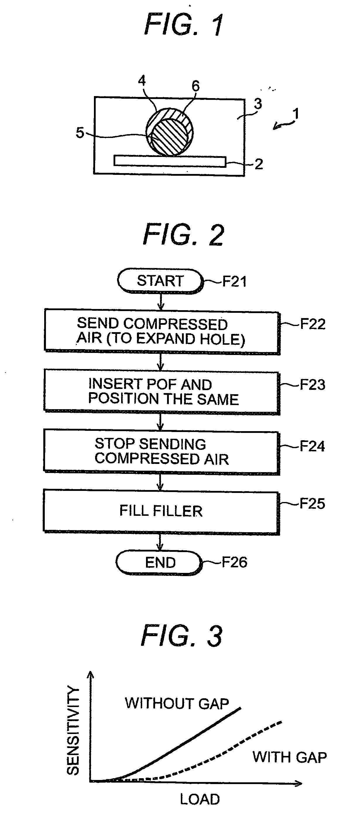
[0045] In optical fiber sensor 1 as shown in FIG. 1, stress concentration plate 2 which has the press punched hole is molded with molded member 3. Plastic fiber (POF) 5 for load (impact) detection is inserted in insertion hole 4 of molded member 3, and Filler (gap material) 6 is filled in the gap between molded member 3 and POF 5.
[0046] Stress concentration plate 2 is formed like an elongated plate. Moreover, a plurality of press punched hole are formed at regular intervals along a long direction of stress concentration plate 2. Stress concentration plate 2 makes it easy for POF 5 to deform by concentrating and transferring the stress based on the load applied to sensor 1 through the press punched hole. The corrugated plate to which the corrugating process is applied may be used as stress concentration plate 2.
[0047] Molded member 3 consists of synthetic resin or synthetic rubber. Insertion hole 4 is formed along a long direction (a direction perpendicular to the paper of FIG. 1) ...
second embodiment
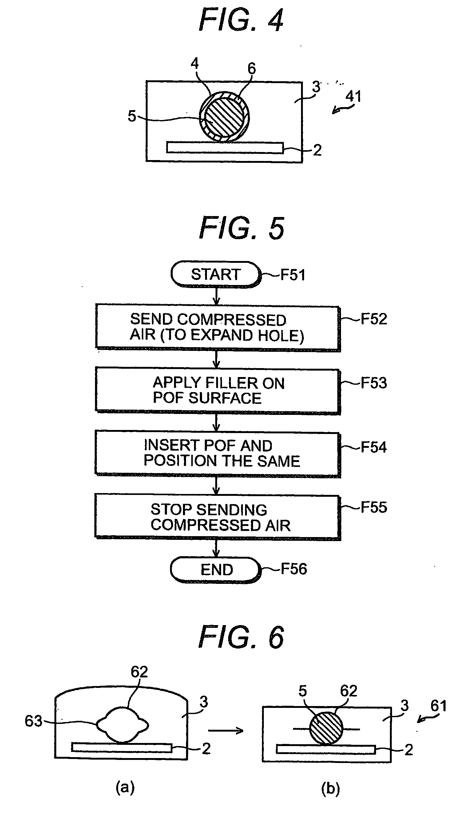
[0061] A second embodiment will be explained next by referring to FIG. 4.
[0062] While sensor 1 of FIG. 1 is made by filling filler 6 to the gap between molded member 3 and POF 5 after POF 5 is inserted in the insertion hole, optical fiber sensor 41 of FIG. 4 is made by inserting POF 5 in insertion hole 4 after filler is applied on POF 5, and burying said gap. Other configuration of sensor 41 is the same as sensor 1.
[0063] A method of manufacturing sensor 41 will be explained with reference to FIG. 5.
[0064] At the start (F51), stress concentration plate 2 has been molded with molded member 3 as shown in FIG. 4, and insertion hole 4 has been formed in molded member 3 beforehand. First of all, the compressed air is sent to insertion hole 4, and insertion hole 4 is expanded (F52). While applying filler 6 on the surface of POF 5 in the state, or after filler 6 is applied on the surface of POF 5 beforehand in another process (F53), this is inserted in insertion hole 4 and POF 5 is settl...
third embodiment
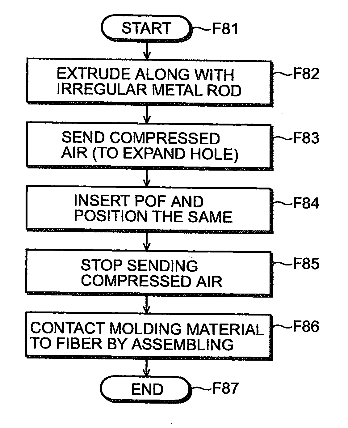
[0066] A third embodiment will be explained next.
[0067] Optical fiber sensor 61 is made as shown in FIG. 6(b). The compressed air is sent to insertion hole 62, and insertion hole 62 is expanded as shown in FIG. 6(a). POF 5 is inserted in the insertion hole in the state. Then, the compressed air is evacuated, and molded member 3 and POF 5 are brought into full contact in a direction (vertical direction in FIG. 6(b)) where the load is applied. Other configuration of sensor 61 is the same as sensor 1 of FIG. 1.
[0068] More in detail, insertion hole 62 is formed roundly in section, that is smaller than the outside diameter of POF 5. Protruding slit 63 (fillet) is formed on both sides (right and left in FIG. 6(a)) along the overall length of the long direction of the insertion hole 62.
[0069] A method of manufacturing sensor 61 is explained by using FIG. 7 and FIG. 8.
[0070] Irregular shaped metal rod 71 shown in FIG. 7 before manufacturing sensor 61 is prepared. Irregular shaped metal r...
PUM
| Property | Measurement | Unit |
|---|---|---|
| Length | aaaaa | aaaaa |
| Pressure | aaaaa | aaaaa |
| Diameter | aaaaa | aaaaa |
Abstract
Description
Claims
Application Information