
Warm air furnace baselining and diagnostic enhancements using rewritable non-volatile memory

a warm air furnace and non-volatile memory technology, applied in the field of fault detection in warm air furnaces, can solve the problems of affecting the expected life of replaceable components of furnaces, affecting the operation of heating equipment, so as to achieve more effective troubleshooting and more robust

Inactive Publication Date: 2006-12-07
HONEYWELL INT INC
View PDF10 Cites 13 Cited by
  • Summary
  • Abstract
  • Description
  • Claims
  • Application Information

AI Technical Summary

Benefits of technology

[0006] The present invention provides an apparatus for warm air furnace diagnostic enhancements and a method for using those enhancements for baselining and more effective troubleshooting. Generally, various embodiments may meet a number of objectives, including: ensuring a more robust furnace installation at a customer premises; dynamically identifying elements of the furnace that may be subject to future fault; and identifying and / or diagnosing current faults. Of course, some embodiments may meet other objectives or have other uses.
[0007] In an exemplary embodiment, a warm air furnace (“furnace”) is equipped with a Flash based microcontroller or EEPROM memory with a microcontroller to retain data in a non-volatile state. Prior to shipment from a manufacturing facility, factory test values for the furnace are measured to create a factory baseline. The measurement may involve passing the furnace through a predetermined furnace test cycle, and obtaining measures during the test cycle, for instance. As examples of potential measurements taken, key baseline furnace performance indicia to retain includes but is not limited to flame current, hot surface ignition (HSI) current, inducer current, fan current, pressure switch open and close times, and heat exchanger rates of temperature rise. These data are stored in the memory of the furnace and are accessible by a technician at installation.
[0008] During installation, measurements may be taken of the performance indicia and compared to the factory baseline. Variations from the factory baseline may indicate improper installation or damage during shipment. Alternatively, the variations may indicate that a maintenance schedule of the installed furnace should be revised or reconsidered. Thus, according to an embodiment, the furnace may determine that a variation is outside of a predetermined range of acceptable variations and, as a result, modify the maintenance schedule to recommend more immediate maintenance. An indication may be provided to a technician or furnace user of the modified maintenance schedule.
[0009] Even with proper installation, the installation baseline measures may differ from the factory baseline measures—for example, air flow rates may depend upon duct-work configuration and building size, likewise, customized furnace options may also cause installation baseline measures to differ from their factory based counterparts. In a further embodiment, an installation baseline is created during installation by measuring the baseline furnace performance indicia and storing those indicia in the memory of the furnace. The installation baseline is useful for predicting wear-out of key system components and for helping in diagnosis of fault conditions. According to the embodiment, the baseline installation indicia are then compared with later obtained indicia and with the run-time counter. The maintenance schedule of the furnace may then be modified based on the comparison.
[0010] In yet another embodiment, the apparatus compares the stored factory baseline and installation baseline and further compares those figures to later obtained measures to determine the performance of the furnace. In another embodiment, periodic measurements are taken of the performance indicia and of run-time counters to help predict system degradation. Such time-series information is also useful for determining whether a particular problem is due to acute failure or to a gradual decline in performance.
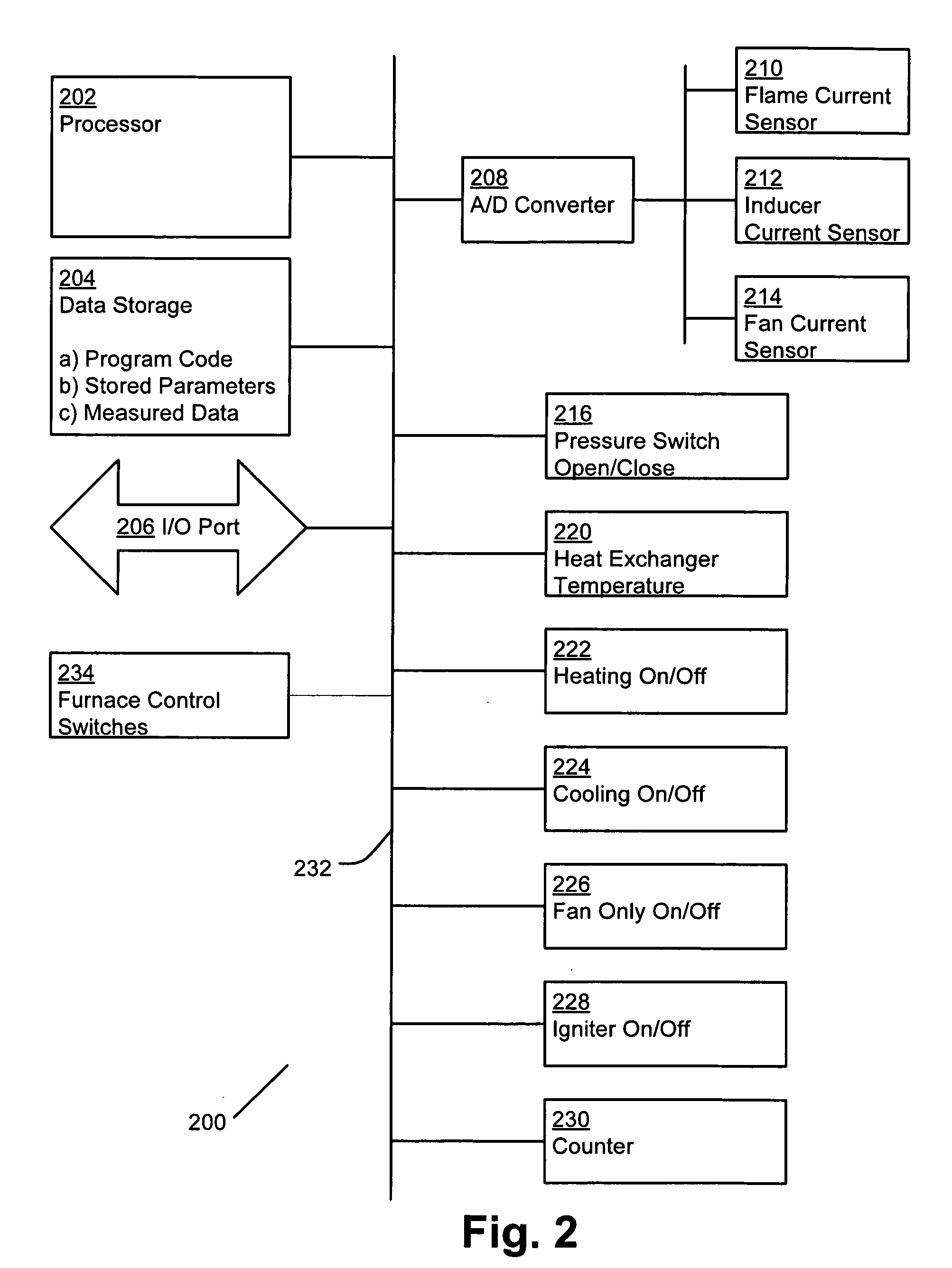
[0011] According to the preferred embodiment, the warm are furnace includes a data storage and a processor. The data storage may be used to store furnace performance data as well as instructions that are executable by a processor. Sensing circuitry is also provided for obtaining furnace performance data during operation of the warm air furnace. These various elements of the furnace may be communicatively linked through a data bus. The instructions stored in data storage may be machine language programs for obtaining readings from the sensing circuitry, storing the readings in data storage, comparing the various readings, and updating a maintenance schedule based upon the comparisons, for instance.

Problems solved by technology

Such diagnosis and repair is often difficult due to the complexity of modern heating, ventilation, and / or cooling systems.
In addition, the individual operating conditions of the furnace-home combination may alter the expected life of replaceable components of the furnace.
Variations from the factory baseline may indicate improper installation or damage during shipment.

Method used


Image

  • Warm air furnace baselining and diagnostic enhancements using rewritable non-volatile memory
  • Warm air furnace baselining and diagnostic enhancements using rewritable non-volatile memory
  • Warm air furnace baselining and diagnostic enhancements using rewritable non-volatile memory

Examples


Embodiment Construction

Exemplary Warm Air Furnace and Control

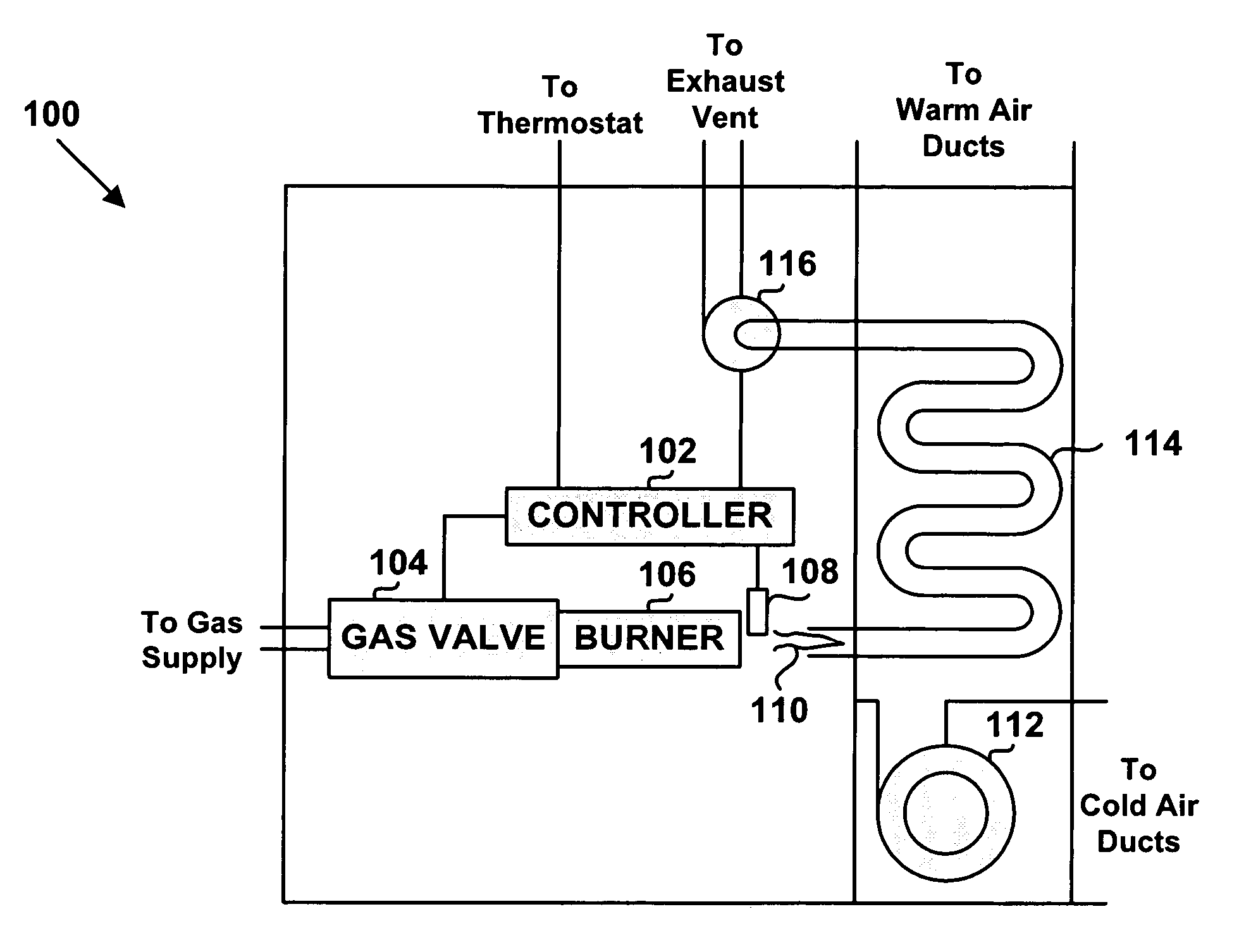
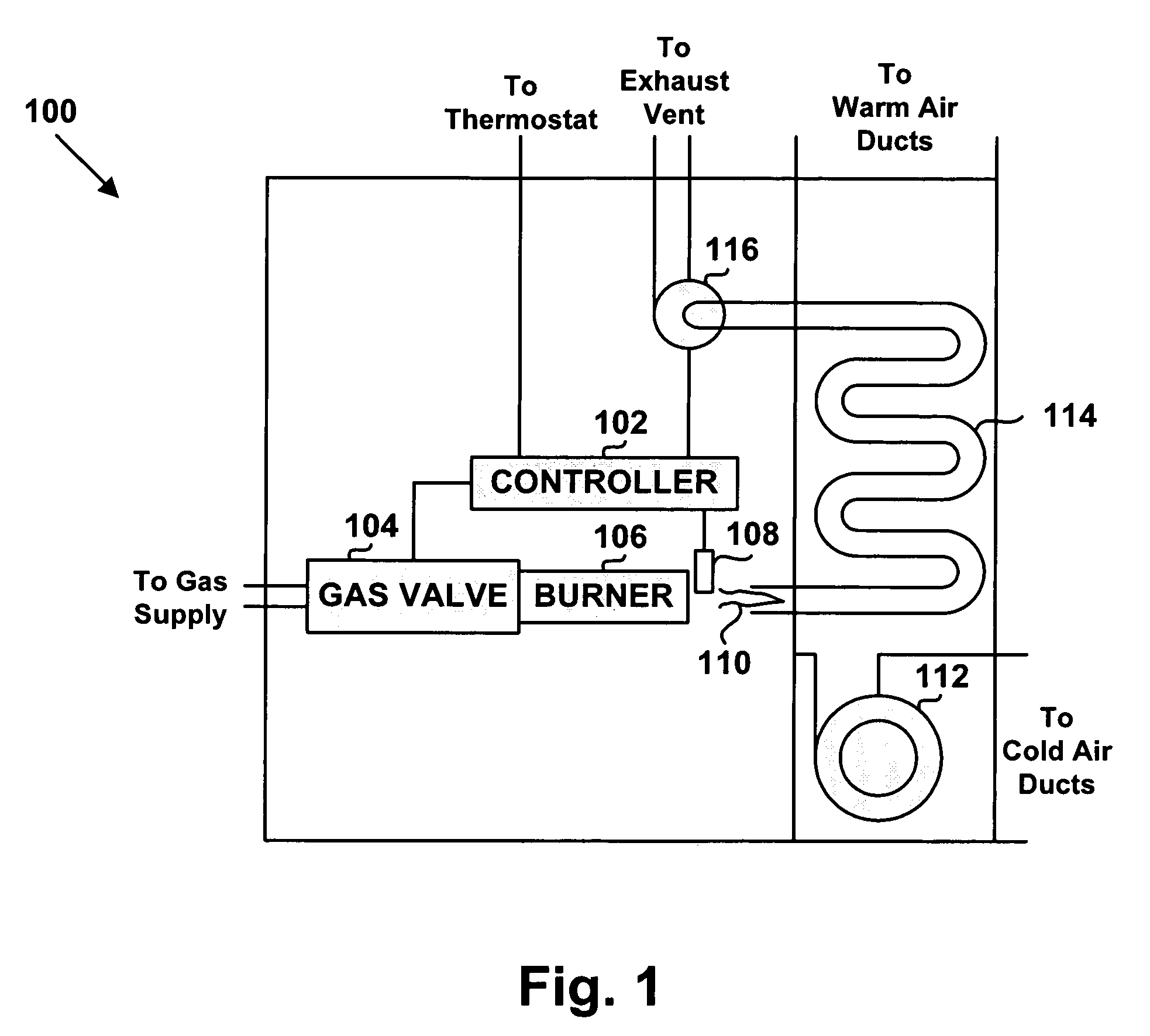
[0016]FIG. 1 shows a simplified block diagram of a warm air furnace 100. The warm air furnace 100 includes a controller 102, a gas valve 104, a burner 106, an ignition element 108, a circulator fan 112, a heat exchanger 114, and a combustion air blower 116, which is also referred to as an inducer. The warm air furnace 100 may include additional components not shown in FIG. 1, such as sensors for detecting temperature and pressure, and filters for trapping airborne dirt. Furthermore, warm air furnaces have various efficiency ratings. Additional components may be necessary to achieve different levels of efficiency.

[0017] The warm air furnace 100 depicted in FIG. 1 is fueled by natural gas. However, the warm air furnace 100 may be fueled by other fossil fuels, such as oil and propane. Different fuel sources may require different components in the warm air furnace 100. For example, a warm air furnace fueled by oil may include an oil pump.

[0018] ...


PUM


Abstract

A warm-air furnace is adapted to provide diagnostic enhancements and more robust installation. In an embodiment, sensing equipment aboard the furnace is used to determine a first performance metric during installation of the furnace. That performance metric is then compared with a baseline metric that may have been obtained at a factory in order to obtain a performance variation value. At least partially in response to the performance variation, a notification is provided to a user. The notification may be an indication of poor installation or shipping damage, present failure and / or predicted future failure, for instance.

Description

BACKGROUND FIELD OF THE INVENTION [0001] The present invention relates generally to warm air furnaces, and more particularly, to fault detection in a warm air furnace. BACKGROUND OF THE INVENTION [0002] Many houses and other buildings use warm air furnaces to provide heat. Generally, these furnaces operate by heating air received through cold air or return ducts and distributing the heated air throughout the building using warm air or supply ducts. A circulation fan, operated by an alternating current (AC) permanent-split-capacitor (PSC) motor, directs the cold air into a heat exchanger, which may be composed of metal. The heat exchanger metal is heated using a burner that burns fossil fuels. The burner is ignited with an ignition device, such as an AC hot surface ignition element. The air is heated as it passes by the hot metal surfaces of the heat exchanger. After the air is heated in the heat exchanger, the fan moves the heated air through the warm air ducts. A combustion air blo...

Claims


Application Information

Patent Timeline
Patent Type & Authority Applications(United States)
IPC IPC(8): F23N5/20
CPCF23N5/20
Inventor HILL, BRUCE L.STRAND, ROLF L.SCHULTZ, MICHAEL W.CUEVA, VICTOR J.
Owner HONEYWELL INT INC
Learn More