
Gun barrel cleaning device with quick-detachable cleaning implement

a cleaning device and cleaning implement technology, applied in the direction of weapon cleaning, pipe units with cleaning apertures, weapons, etc., can solve the problems of misplaced or lost cleaning implements, prone to thread damage or stripping, and inconvenient thread connection of the cleaning rod system, so as to facilitate the rotation of the cleaning implement and be easily detachable from the handle

Inactive Publication Date: 2006-12-14
MICHAELS OF OREGON
View PDF31 Cites 56 Cited by
  • Summary
  • Abstract
  • Description
  • Claims
  • Application Information

AI Technical Summary

Benefits of technology

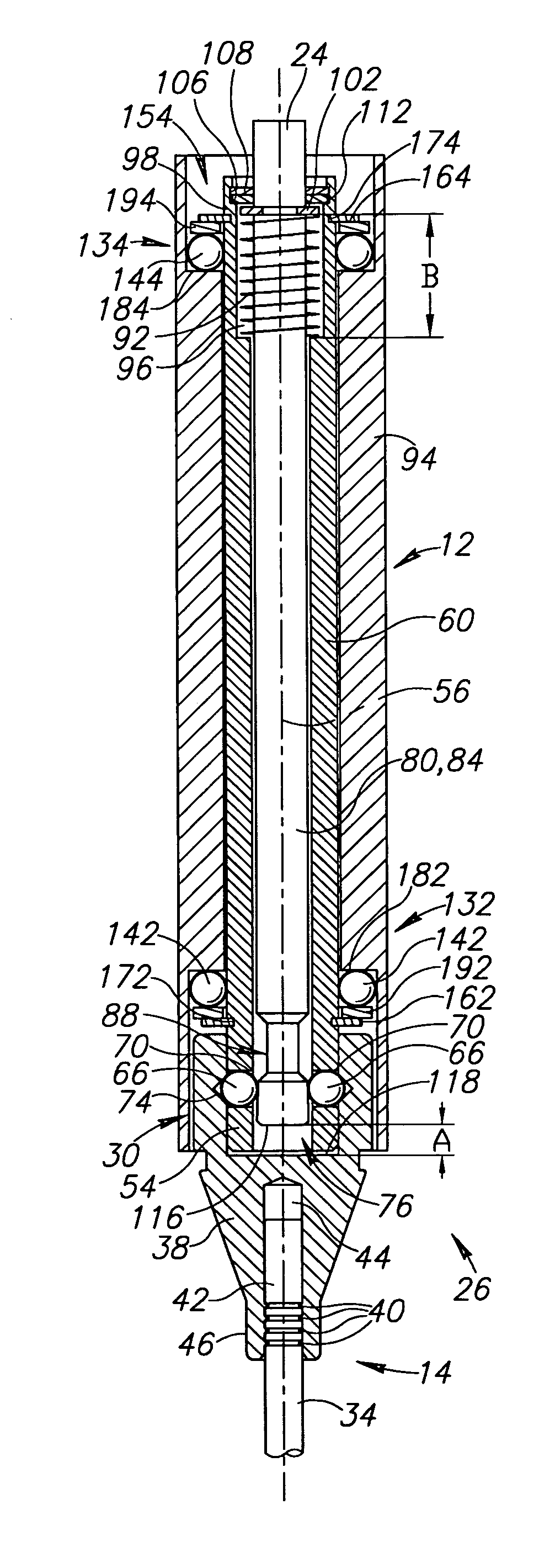
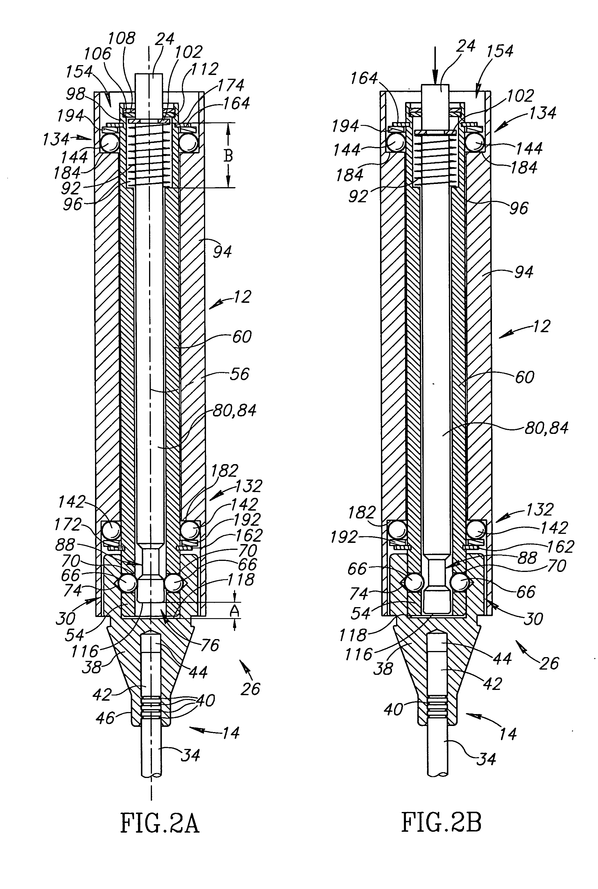
[0007] A gun barrel cleaning device includes a quick-detachable coupling mechanism releasably coupling a handle to a cleaning implement that may be sized for insertion into and cleaning of a gun barrel bore. The quick-detachable coupling mechanism includes a male part having an axis, a female part receiving the male part coaxially therein, and a latching device slidably movable between an unlatched position and a latched position. When the latching device is in the unlatched position, the cleaning implement is readily detachable from the handle. When the latching device is in the latched position, the cleaning implement is prevented from being detached from the handle. A thrust bearing is preferably provided for supporting the cleaning implement on the handle and for facilitating rotation of the cleaning implement about its axis relative to the handle.

Problems solved by technology

However, the threaded connection used in these systems is somewhat inconvenient, subject to inadvertent loosening during use, and prone to damage or stripping of threads.
The various sizes of tools and collets required to fit cleaning rods and implements of various diameters are subject to being misplaced or lost due to their small size.
However, the cleaning tool of Sipple et al. is not suitable for cleaning the bore of a gun barrel and, due to the structure of the latch mechanism, the cleaning implements are not rotatable relative to the handle when attached thereto.

Method used


Image

  • Gun barrel cleaning device with quick-detachable cleaning implement
  • Gun barrel cleaning device with quick-detachable cleaning implement
  • Gun barrel cleaning device with quick-detachable cleaning implement

Examples


Embodiment Construction

DETAILED DESCRIPTION OF PREFERRED EMBODIMENTS

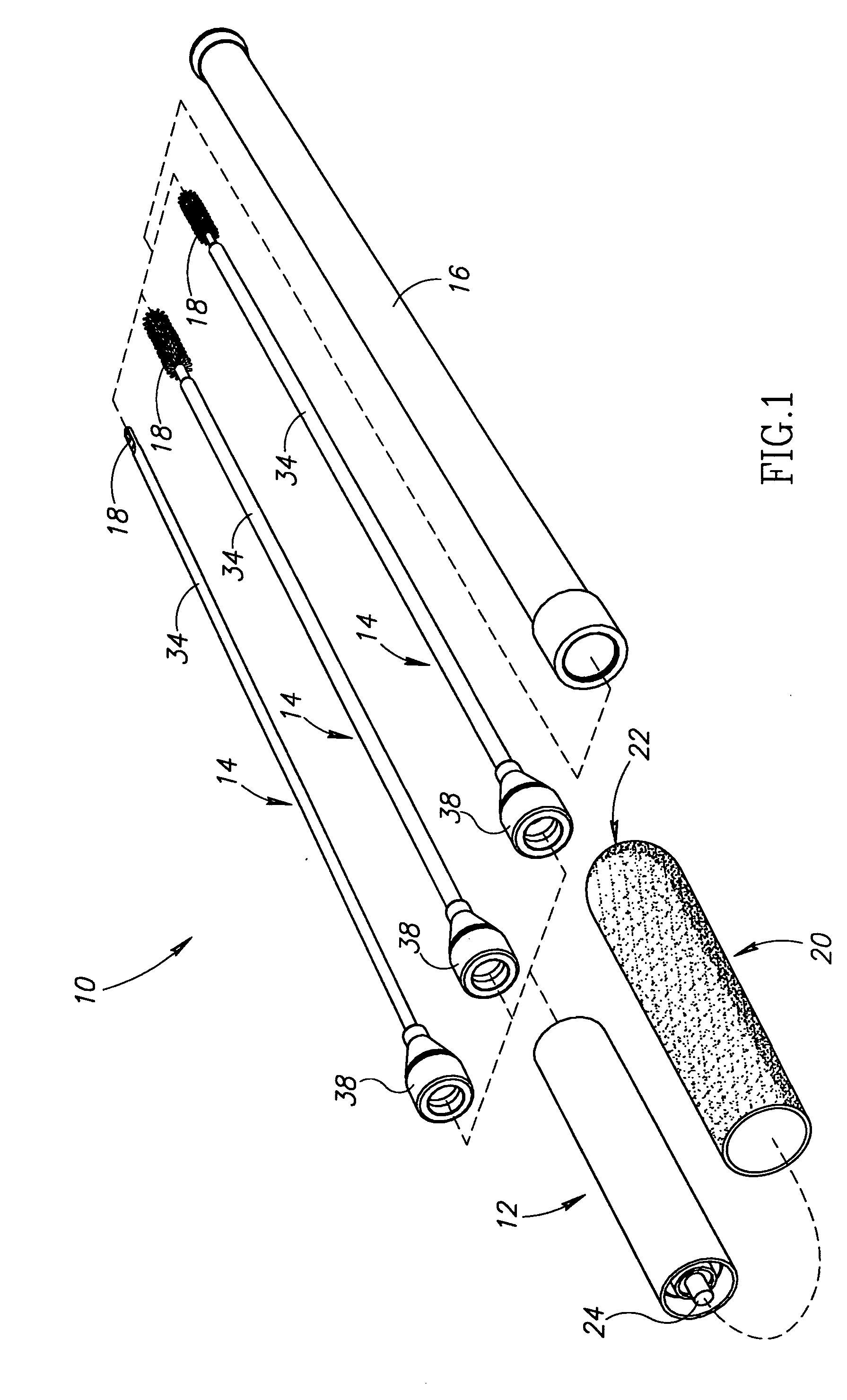
[0016] With reference to FIG. 1, a gun cleaning kit 10 includes a handle 12 and a variety of gun cleaning implements 14 interchangeably connectable to the handle. Each cleaning implement 14 may be inserted into a protective storage sheath 16 for storage and shipping, as described below in detail with reference to FIG. 3. Cleaning implements 14 may be provided in a variety of different lengths and gages sized to clean firearms of different calibers and various types of gun barrel bores. In addition, cleaning implements 14 may be equipped with a variety of different brushes, swabs, or jags at their working ends 18 for different cleaning applications. An optional grip 20 is press fit or otherwise secured around handle 12 to provide a comfortable and slip-resistant gripping surface for handle 12. Each of the cleaning implements 14 is preferably formed of a rigid, one-piece rod 34 for precision and durability. However, in some embodiments (not...


PUM


Abstract

A gun barrel cleaning device includes a quick-detachable coupling mechanism releasably coupling a handle to a cleaning implement for cleaning a gun barrel bore. A thrust bearing is preferably provided for supporting the cleaning implement on the handle and for facilitating axial rotation of the cleaning implement relative to the handle. The gun barrel cleaning device may comprise part of a gun barrel cleaning kit, which may include a variety of different cleaning implements. A novel sheath for storing a gun barrel bore-cleaning implement is also disclosed.

Description

TECHNICAL FIELD [0001] This application relates to gun barrel cleaning devices. BACKGROUND OF THE INVENTION [0002] Known gun barrel cleaning devices include a handle connected to an elongate rod or flexible cable, cord, or other length of material supporting a brush, swab, or other type of cleaning jag that is pushed or pulled through the bore of the gun barrel to remove residue or debris. In most known cleaning devices, the rod or other cleaning implement is either permanently connected or threadably attached to the handle. To prevent damage to rifled surfaces of the bore, the cleaning implement should be allowed to rotate as it moves through the barrel. In some bore cleaning devices, such as those disclosed in U.S. Pat. Nos. 1,556,494 of Cooper and 3,208,302 of Lewis et al., the handle includes one or more bearings for reducing frictional resistance to rotation of the cleaning implement about its longitudinal axis relative to the handle under axial loading conditions that occur wh...

Claims


Application Information

Patent Timeline
Patent Type & Authority Applications(United States)
IPC IPC(8): F41A29/00
CPCF41A29/02
Inventor PETERSON, THOMAS K. M.
Owner MICHAELS OF OREGON
Learn More