Automatic stirring system

a technology of automatic stirring and stirring bowl, which is applied in the direction of rotary stirring mixer, baking plant, cooking vessel, etc., can solve the problems of non-homogeneous food products, inconsistent taste, food items may become burnt, etc., and achieve the effect of increasing the durability and longevity of the automatic stirring bowl

Inactive Publication Date: 2006-12-14
NOTTINGHAM SPIRK DESIGN ASSOCS
View PDF8 Cites 36 Cited by
  • Summary
  • Abstract
  • Description
  • Claims
  • Application Information

AI Technical Summary

Benefits of technology

[0009] In yet another embodiment, the automatic stirring system would include an aluminum or stainless steel housing, ring gear, and stirring vanes to increase the durability and longevity of the automatic stirring system.

Problems solved by technology

If due to any number of reasons the stirring process is neglected, avoided, or abandoned, the food item may become burnt because of localized overheating of the food mixture.
At the very least, a lack of stirring will result in a non-homogenous food product that is unevenly cooked thereby having an inconsistent taste.
It is likely that the resulting food item will be offensive to the user or cook and will end up being thrown away.
One disadvantage involves the overall size and complexity of these systems.
These permanent type installations are unattractive and often consume precious work space.
Another disadvantage involves the proximity of the stirring elements to the cooking vessel.
Often the stirring elements neglect to fully agitate the food mixture that may become attached to the inner wall and bottom surfaces of the cooking vessel.
Yet another disadvantage relates to the design of the stirring elements.
As explained herein, a flat stirring element is less effective at stirring because it tends to push fluid and other food items toward the center of the cooking vessel.
This may result in a swirling vortex where only certain ingredients will be mixed.
Still another disadvantage involves the overall orientation of the various components required to stir the contents of the cooking vessel.
Most stirring systems consume most if not all of the opening of the cooking vessel.
This makes it extremely difficult for the user to observe, add ingredients to, or remove portions of the food mixture while these stirring systems are attached or operating.
Yet another disadvantage involves the user's ability to adjust the speed of the stirring system of the system.
Some systems may offer various speed settings, however, these speed settings are often too slow or too fast to obtain optimal mixing.

Method used


Image

  • Automatic stirring system
  • Automatic stirring system
  • Automatic stirring system

Examples


Embodiment Construction

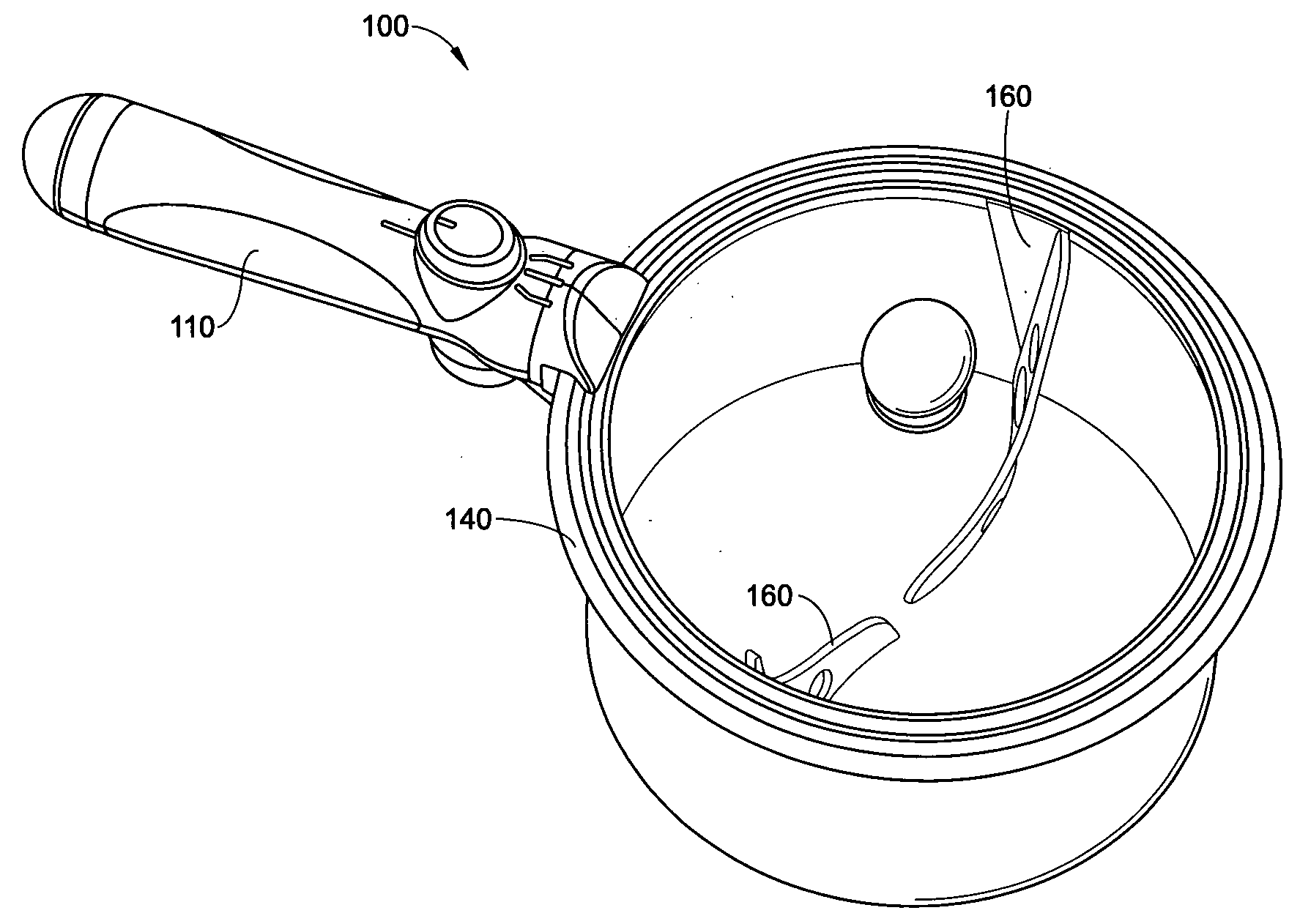
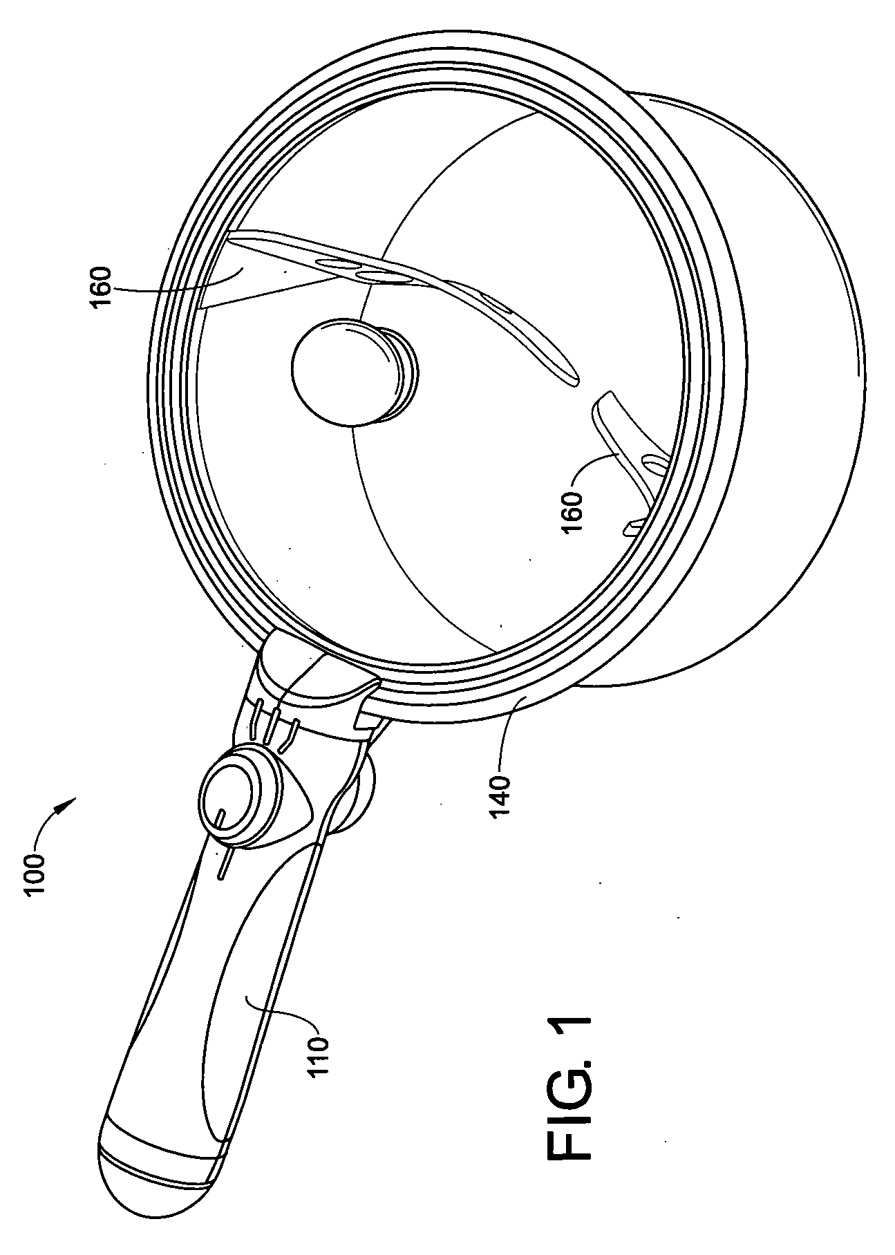
[0023] With reference to FIG. 1, a first embodiment of an automatic stirring system 100-is shown. The stirring system 100 generally includes a housing 110, a drive assembly 120 (FIG. 5), and a stirring vane assembly 135. The stirring vane assembly 135 includes a ring gear 140 and a pair of stirring vanes 160.

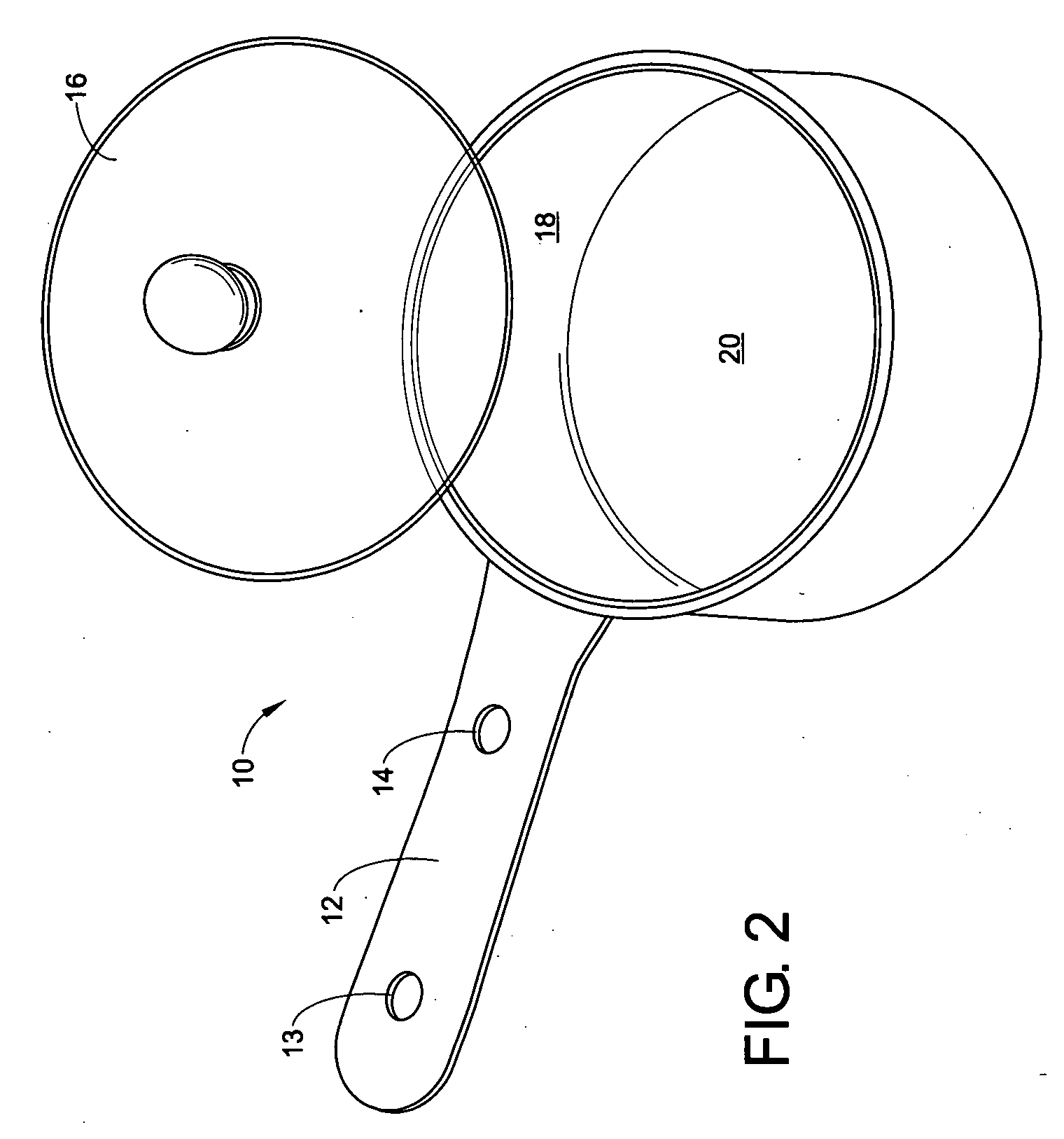
[0024] With reference to FIGS. 1 and 2, the housing 110 is adapted to attach to the upper portion of an existing handle 12 of a cooking vessel or sauce pan 10. The cooking vessel 10 includes a lid 16, an inner wall surface 18 and an inner bottom surface 20. In addition, the handle 12 includes at least one aperture 14. The housing 110 of the automatic stirring system is designed to engage the aperture 14 of the handle 12 of the cooking vessel 10. Also, the ring gear 140 and stirring vanes 160 are adapted to fit within the cooking vessel 10. Specifically, the stirring vanes 160 are designed to come into close proximity with the inner wall surface 18 and the inner bottom surface 2...


PUM


Abstract

The present invention relates to an automatic stirring system that is selectively mounted to a cooking vessel. The cooking vessel includes a handle, an opening for receiving food items, and a lid. The automatic stirring system includes a housing mounted to the handle, a ring gear rotatably mounted to the cooking vessel, a drive assembly for rotating the ring gear, and at least one stirring vane attached to the ring gear. In various other embodiments, the automatic stirring system includes at least one forward swept stirring vane, at least one aperture in the stirring vane, a variable speed control unit, and a component orientation that provides substantially unimpeded access to the opening of the cooking vessel.

Description

FIELD OF THE INVENTION [0001] The present invention relates to the art of stirring systems used in the preparation of food items. In particular, the present invention involves an automatic stirring system that may be mounted to a conventional cooking pot, vessel, or pan. BACKGROUND [0002] In preparing various food items a common step usually involves stirring any number of ingredients together. In some cases the stirring process must be done continuously as is common in the preparation of certain soups, sauces, and puddings. If due to any number of reasons the stirring process is neglected, avoided, or abandoned, the food item may become burnt because of localized overheating of the food mixture. At the very least, a lack of stirring will result in a non-homogenous food product that is unevenly cooked thereby having an inconsistent taste. It is likely that the resulting food item will be offensive to the user or cook and will end up being thrown away. [0003] While stirring systems t...

Claims


Application Information

Patent Timeline
Patent Type & Authority Applications(United States)
IPC IPC(8): A21B7/00
CPCA47J36/165
Inventor SAUNDERS, CRAIG M.ANTONETTI, SARAH N.
Owner NOTTINGHAM SPIRK DESIGN ASSOCS
Why Eureka
Try Eureka