Solenoid valve with fitted shoulder

Active Publication Date: 2006-12-14
BONTAZ CENT
View PDF16 Cites 28 Cited by
  • Summary
  • Abstract
  • Description
  • Claims
  • Application Information

AI Technical Summary

Benefits of technology

[0016] A first problem proposed by the invention is to design a solenoid valve structure that can b

Problems solved by technology

This mode of coupling between the valve body and the electromagnetic actuator, via a protruding shoulder, is costly to produce, just as much in the material used as in the labor and in machine time.
This method of plunge-cut precision grinding is therefore costly in machine time, in labor and in inspections.
Consequently, the production of a valve body with protruding shoulder has been hitherto costly both during the rough machining and during the precision grinding in order to achieve a valve b

Method used


Image

  • Solenoid valve with fitted shoulder
  • Solenoid valve with fitted shoulder
  • Solenoid valve with fitted shoulder

Examples


Embodiment Construction

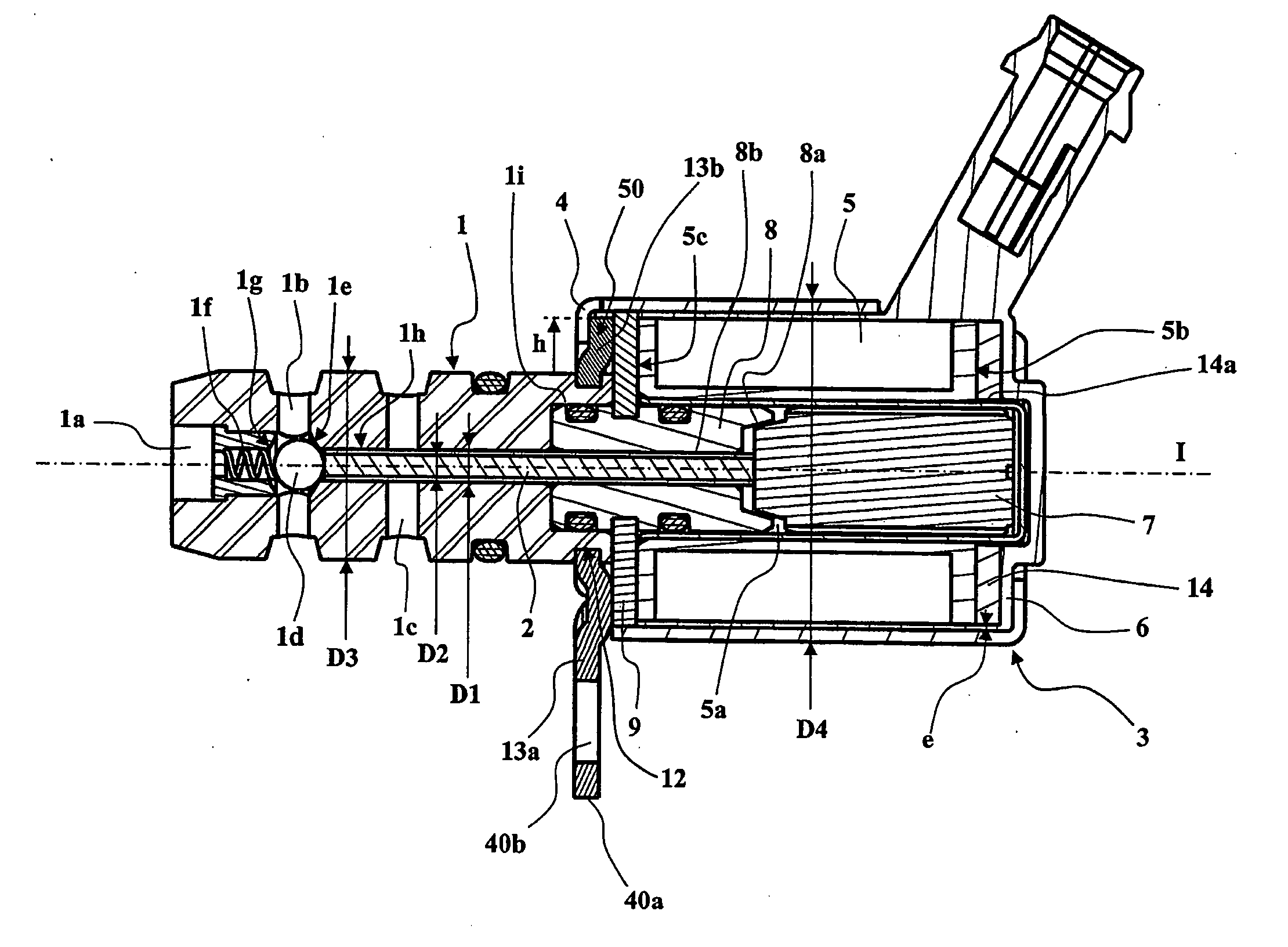
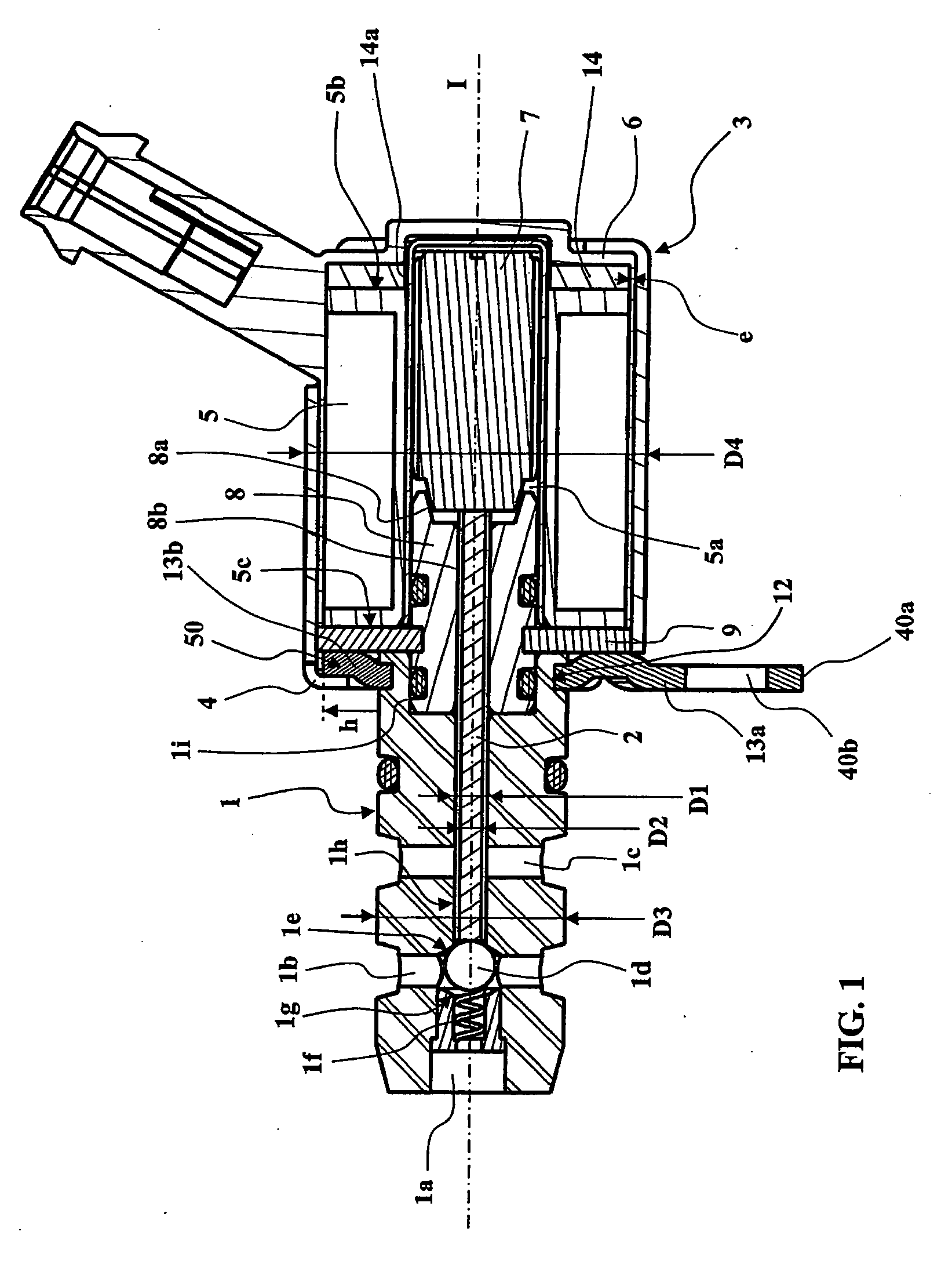
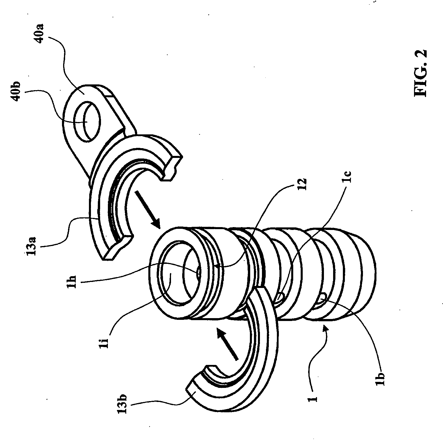
[0047] In the embodiment represented in FIGS. 1 and 2, a solenoid valve for controlling the flow of a fluid in a hydraulic circuit according to the invention comprises in particular a valve body 1 furnished with an axial fluid duct 1a and two transverse fluid ducts 1b and 1c. The valve body 1 comprises a stopper 1d in the shape of a ball to allow or prevent the flow of fluid in the fluid ducts 1a, 1b and 1c. The ball 1d is held pressing against a first seat 1e by a spring 1f. The ball 1d may however be pushed away from the first seat 1e against a second opposite seat 1g.

[0048] When the ball 1d is pressing against the first seat 1e, the latter prevents any communication between the transverse fluid duct 1b and the transverse fluid duct 1c. The fluid may then circulate between the transverse duct 1b and the axial duct 1a. On the other hand, when the ball 1d is pressing against the second seat 1g, the latter blocks off the axial fluid duct 1a and authorizes the fluid to circulate betw...


PUM


Abstract

Solenoid valve for controlling the flow of a fluid in a hydraulic circuit, comprising a valve body having at least one fluid duct, a stopper for allowing or preventing the flow of fluid in the fluid duct, a mechanical connection to actuate the stopper, an electromagnetic actuator arranged to actuate the mechanical connection, and a coupling between the electromagnetic actuator and the valve body via a jacket surrounding the electromagnetic actuator and engaged on a shoulder of the valve body. The jacket holds the electromagnetic actuator in axial engagement against the valve body in a direction of engagement. The shoulder comprises two matching half-washers engaged radially in a peripheral groove of the valve body.

Description

TECHNICAL FIELD OF THE INVENTION [0001] The present invention relates to solenoid valves for controlling the flow of a fluid in a hydraulic circuit, such as the solenoid valves used to control the flow of liquid for cooling and lubricating pistons in the engines of motor vehicles. [0002] In a general manner, and as described for example in documents JP2000-136888A, US 2004 / 0113112A1 or U.S. Pat. No. 4,578,662 A, solenoid valves for controlling the flow of a fluid in a hydraulic circuit comprise: [0003] a valve body, having at least one fluid duct, a stopper for allowing or preventing the flow of fluid in the fluid duct and a mechanical connection to actuate the stopper, [0004] an electromagnetic actuator arranged to actuate the mechanical connection, [0005] a coupling between the electromagnetic actuator and the valve body, via a jacket surrounding the electromagnetic actuator and engaged with a shoulder protruding from the valve body, that holds the electromagnetic actuator in axia...

Claims


Application Information

Patent Timeline
IPC IPC(8): F16K31/02F16K31/06
CPCF16K31/0631Y10T137/86622H01F7/16F16K27/029F16K27/0245
Inventor CHAVANNE, SAMUEL
Owner BONTAZ CENT
Why Eureka
Try Eureka