Passive dynamically stabilizing magnetic bearing and drive unit

a dynamically stabilizing, magnetic bearing technology, applied in the direction of bearings, mechanical energy handling, electrical equipment, etc., to achieve the effect of easy production

Inactive Publication Date: 2006-12-14
SILPHENIX
View PDF20 Cites 30 Cited by
  • Summary
  • Abstract
  • Description
  • Claims
  • Application Information

AI Technical Summary

Benefits of technology

[0007] The bearing according to the invention has the advantage that it is easy to produce and is therewith not expensive.

Problems solved by technology

Hence, there is the problem to provide a passive magnetic bearing of the kind mentioned at the outset which avoids the disadvantages mentioned above at last partially.

Method used


Image

  • Passive dynamically stabilizing magnetic bearing and drive unit
  • Passive dynamically stabilizing magnetic bearing and drive unit
  • Passive dynamically stabilizing magnetic bearing and drive unit

Examples


Embodiment Construction

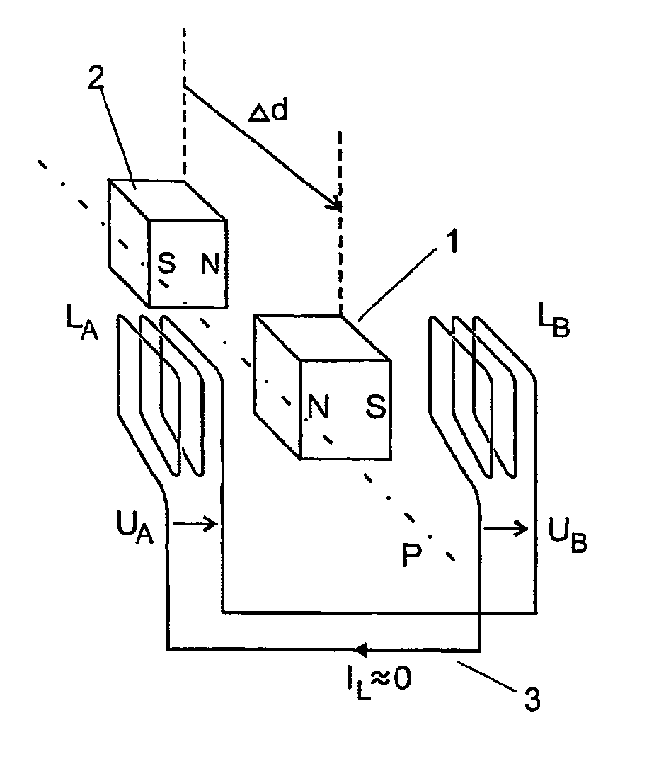
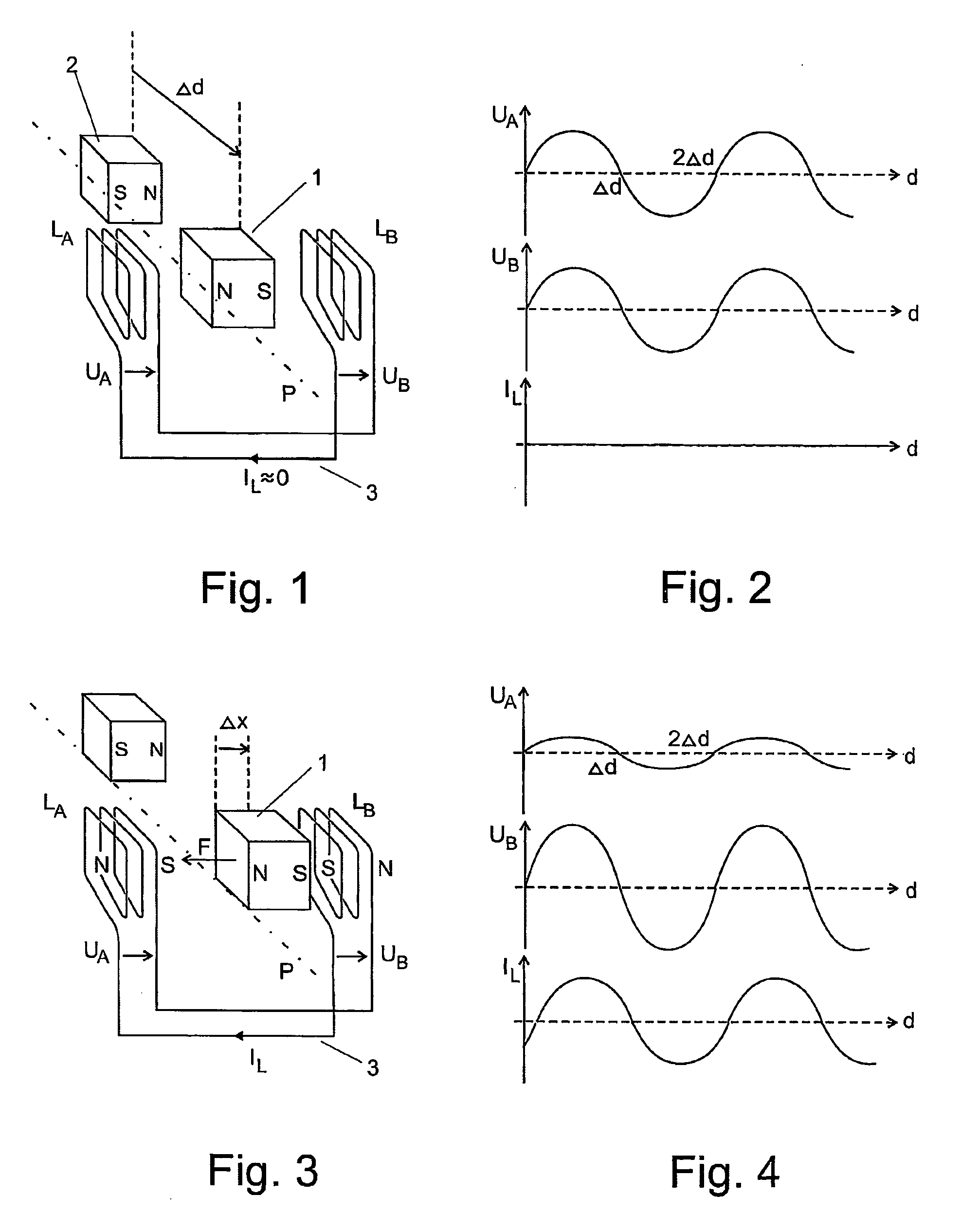
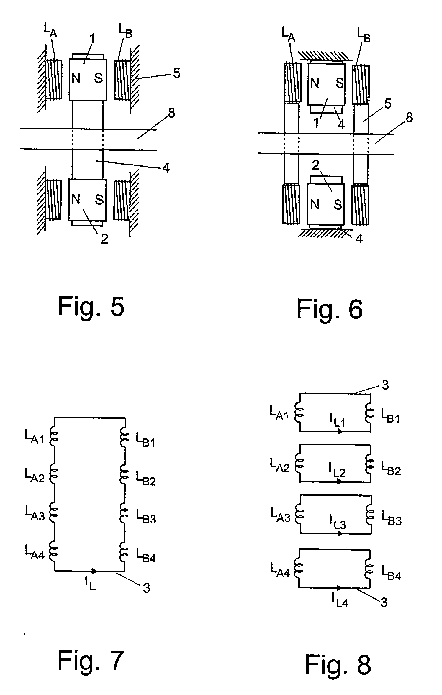
[0029] The principle of the invention is explained referring to FIG. 1 to 4. Different axial bearings based on the principle are described referring to FIG. 5 to 15. The passive magnetic bearing according to the invention can be extended by a drive, which is illustrated referring to FIG. 16 to 20.

[0030] The coils occurring in the different embodiments can be categorized according to their function, for example in “bearing coils” and “drive coils”. In cases, where no such specification is necessary, in particular at the embodiments without drive, for reasons of simplicity the term “coil” is used without an attribute like “bearing” or “drive”.

[0031] The term “polarization axis” used in this document is to be understood as follows: At permanent magnets the polarization axis is the straight line through south and north pole. At coils the polarization axis is the straight line through south and north pole as well, independent of the fact that these do not result until there is a curren...


PUM


Abstract

The passive axial magnet bearing comprises permanent magnets (1, 2) arranged with alternating polarization on a rotor (1, 2, 8). These cause an oscillating flow through the coils (L) on both sides of the rotor (1, 2, 8). All coils (L) are series connected in an electric circuit (3). As long as the rotor (1, 2, 8) rotates in the middle position, no current flows in the electric circuit (3), since the voltages across the coils (L) cancel each other due to the symmetry. However, when the rotor (1, 2, 8) deviates from the center position, a current flows and the coils (L) exert electromagnetically a restoring force on the permanent magnets (1, 2). The bearing can also be equipped with an integrated drive. For this purpose, it is extended by drive coils. The production of the bearing is simple and inexpensive.

Description

CROSS REFERENCES TO RELATED APPLICATIONS [0001] This application claims the priority of Swiss patent application 826 / 02, filed May 16, 2002, the disclosure of which is incorporated herein by reference in its entirety. TECHNICAL FIELD [0002] Passive magnetic bearings are intended for bearing in particular very fast rotating rotors without wear and without substantial energy losses. They can in particular be used at flywheels for energy storage devices. In this, the flywheels are borne radially as well as axially without contact. BACKGROUND ART [0003] Conventional mechanical bearings, as for example ball bearings, are at high speed very loud, have to be lubricated, have a large wear and are not suited for vacuum or low temperatures. Active magnetic bearings have an ongoing need for energy and are, due to the necessary position sensors, current sources and control electronics, very expensive. Passive magnetic bearings with superconductors are expensive as well and complex to produce. I...

Claims


Application Information

Patent Timeline
Patent Type & Authority Applications(United States)
IPC IPC(8): H02K7/09F16C39/06
CPCH02K7/09F16C32/0436
Inventor ASPER, HANS K.
Owner SILPHENIX
Why Eureka
Try Eureka