

High-pressure discharge lamp, high-pressure discharge lamp operating apparatus, and illuminating apparatus
- Summary
- Abstract
- Description
- Claims
- Application Information
AI Technical Summary
Benefits of technology
Problems solved by technology
Method used
Image

Examples
example 1
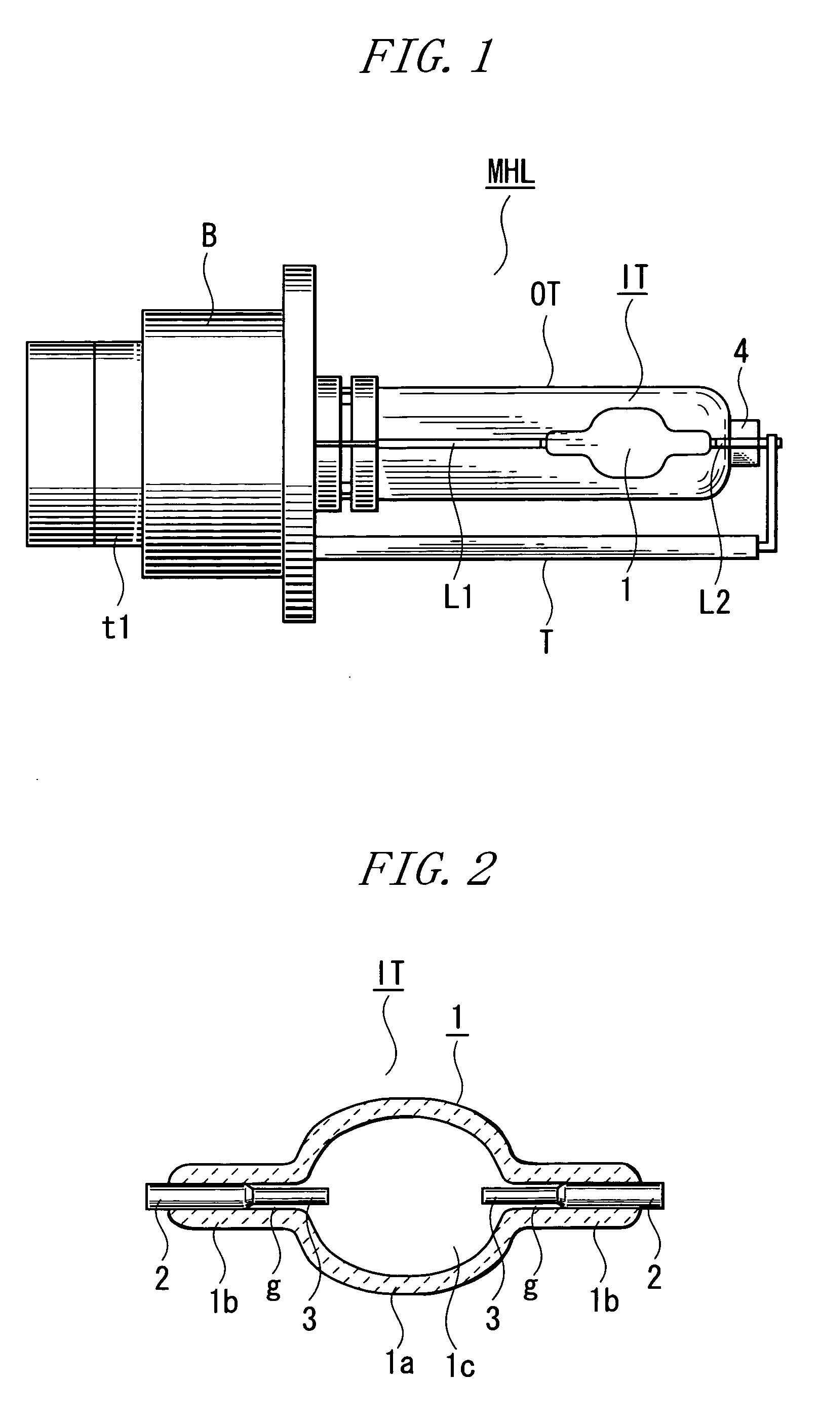
Translucent ceramics discharge vessel: integrally molded and made of translucent alumina ceramics, entire length: 16 mm,
[0172] Surrounding part: maximum inner diameter: 5 mm, thickness: 0.5 mm, and length: 6 mm,
[0173] Opening: inner diameter: 0.7 mm, thickness: 0.5 mm, and length: 5 mm
Current introducing conductor: Nb bar
Electrode: tungsten bar, inter-electrode distance: 4.2 mm
Discharge medium: halide of a luminous metal DyI3—NdI3—CsI=3 mg, lamp voltage forming halide ZnI2=1 mg, rare gas Xel: 0.5 atm
Sealing method: rotating opening is externally irradiated with YAG laser to melt the ceramics in the opening of the translucent ceramics discharge vessel to seal the current introducing conductor to the opening.
Current characteristics: lamp power: 35 W, lamp voltage: 70 V
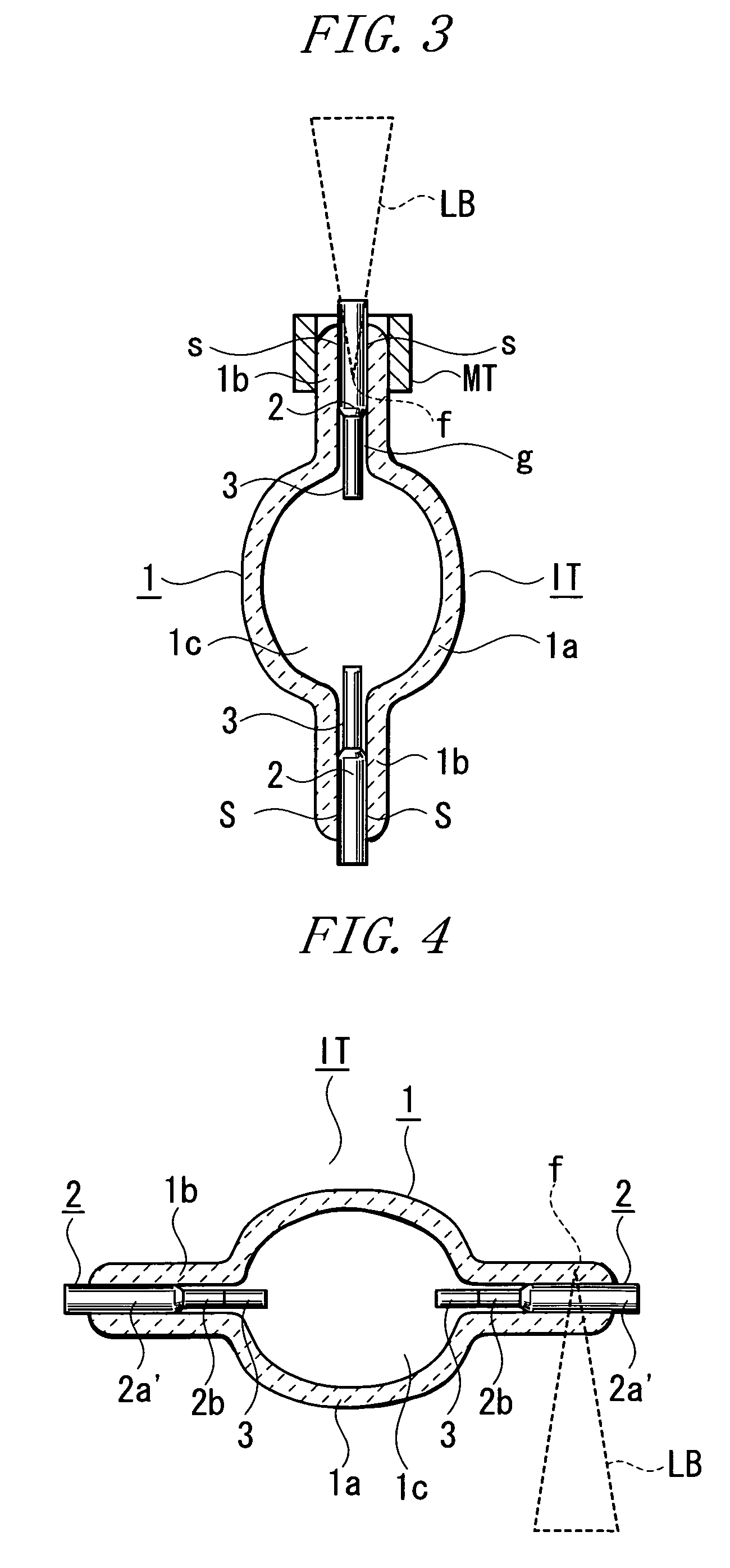
[0174]FIG. 3 is a conceptual drawing showing a second embodiment of the high-pressure discharge lamp of the present invention. In the figure, the same components as those in FIG. 2 are denoted by the same r...
example 2
[0193] The structure shown in FIG. 4 is used.
Current introducing conductor: cermet (Mo-alumina) bar of diameter 0.65 mm+Mo bar of diameter 0.3 mm
Electrode: W bar, inter-electrode distance: 3.0 mm
Seal part: welding mostly occurs in the cermet in the current introducing conductor. Instead of the cermet, the opening may be welded.
Unsealed part: average gap on the discharge space side: 0.05 mm, length along the tube axis: 1.5 mm
Rare gas: Xe at 0.5 atm
The other arrangements are the same as those in Example 1.
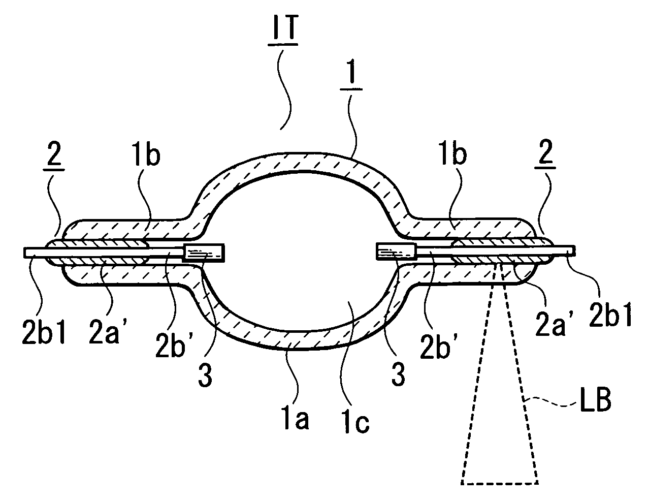
[0194]FIG. 5 is a sectional view of an arc tube according to a fourth embodiment in the high-pressure discharge lamp of the present invention. The fourth embodiment carries out the second to fourth aspects of the present invention.
[0195] In the third embodiment, the current introducing conductor 2 has the series connection structure of the sealing substance bar 2a′, consisting of the cermet, and the halogen-resistant metal bar 2b′. The halogen-resistant metal bar 2b′ pen...
example 3
[0198] The structure shown in FIG. 5 is used.
Current introducing conductor: cermet (Mo-alumina, mixture ratio (mass %): 50 to 50) bar+Mo bar
Unsealed part: average gap: 0.05 mm, length along the tube axis: 1.5 mm
The other arrangements are the same as those in Example 2.
[0199] The average gap in the unsealed part is measured in an area which is adjacent to the seal part and which is not deformed in spite of sealing. The average gap is determined by reducing the difference between the inner diameter of opening of the translucent ceramics discharge vessel and the diameter of the current introducing conductor to half.
[0200]FIG. 6 is a partly cutaway sectional view of an arc tube according to the fifth embodiment in the high-pressure discharge lamp of the present invention. The fifth embodiment corresponds to a variation of the fourth embodiment and thus carries out the second to fourth aspects of the present invention.
[0201] The current introducing conductor 2 has the series con...
PUM
 Abstract
Description
Claims
Application Information