Electromagnetic relay

a technology of electromagnetic relays and electrodes, applied in the field of multipolar electromagnetic relays, can solve the problems of difficult to attach electromagnetic relays to the boards, obstruct the improvement of assembly workability, and the mounting area is large, so as to improve the reliability, reduce the number of electrodes, and reduce the size of the electrodes

Inactive Publication Date: 2006-12-14
ORMON CORP
View PDF11 Cites 40 Cited by
  • Summary
  • Abstract
  • Description
  • Claims
  • Application Information

AI Technical Summary

Benefits of technology

[0012] Further, the plural contact mechanisms are alternately arranged in the upper and lower stage along the moving direction of the moving body, namely, the upper contact mechanism and the lower contact mechanism are alternately arranged in the moving direction. Therefore, the insulating properties can be improved between the adjacent upper and lower contact mechanisms while the downsizing is achieved in the moving direction.
[0025] Thus, the present invention can provide the electromagnetic relay which can be flattened in shape to perform a low profile mounting, downsized for the number of electrodes, and excellent for assembling the internal components.

Problems solved by technology

In the electromagnetic relay disclosed in Japanese Patent Application Laid-Open No. 2000-285782, although a mounting area in a board can be decreased, sometimes it is difficult to attach the electromagnetic relay to the board in a low-profile housing because the electromagnetic relay is relatively higher.
This results in one of causes of obstructing improvement of assembling workability.

Method used


Image

  • Electromagnetic relay
  • Electromagnetic relay
  • Electromagnetic relay

Examples


Embodiment Construction

[0036] Preferred embodiments of the invention will be described below with reference to the accompanying drawings.

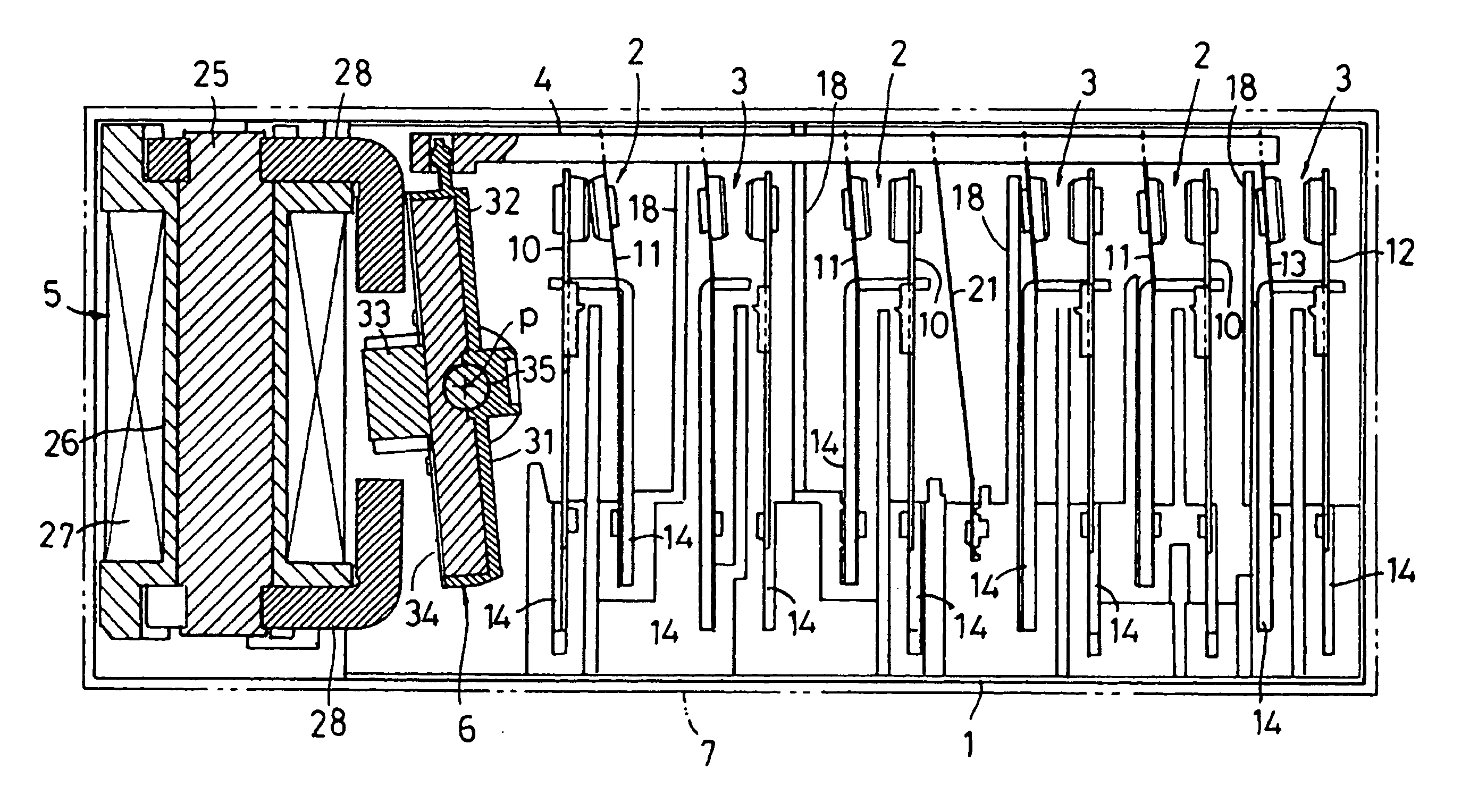
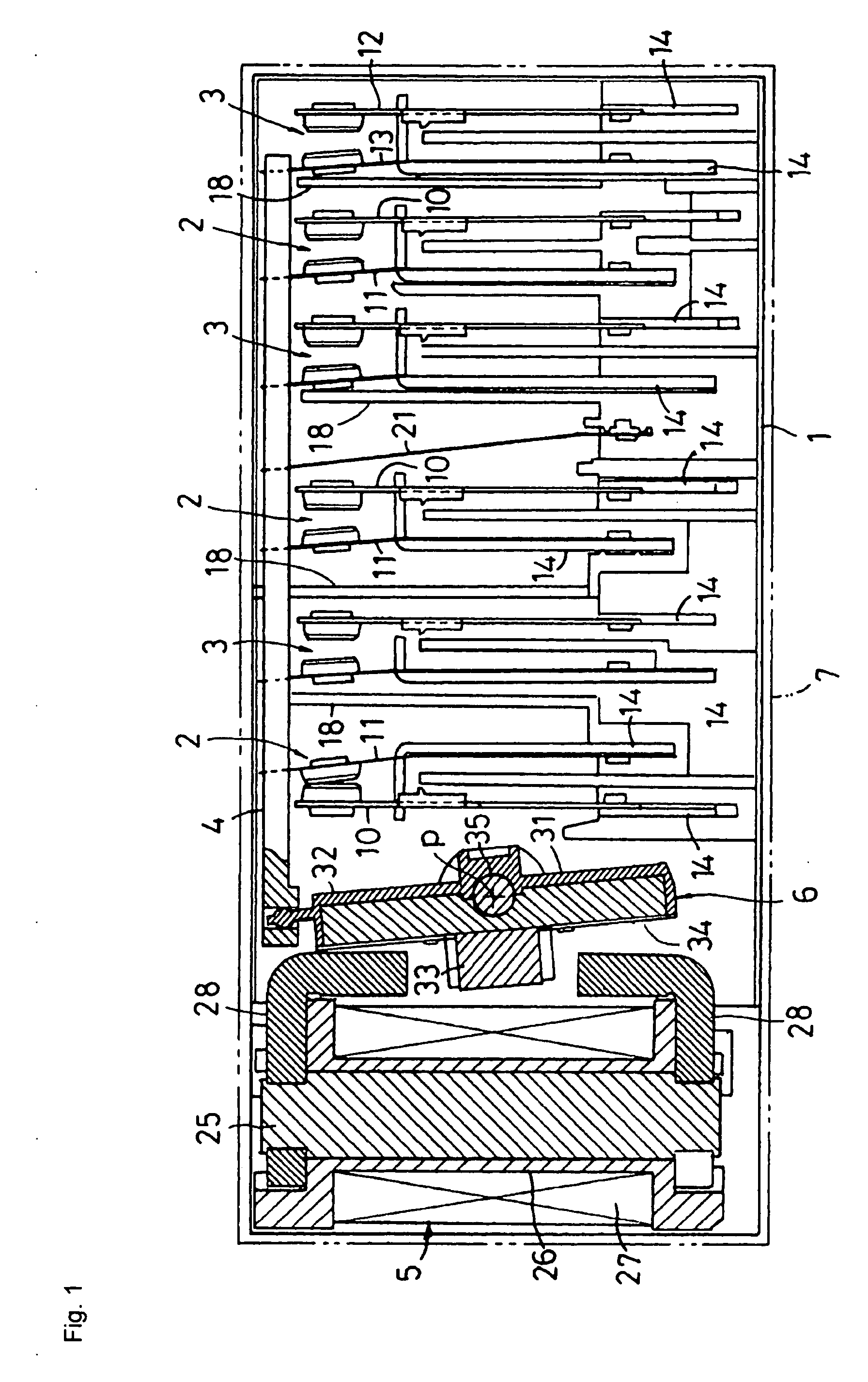
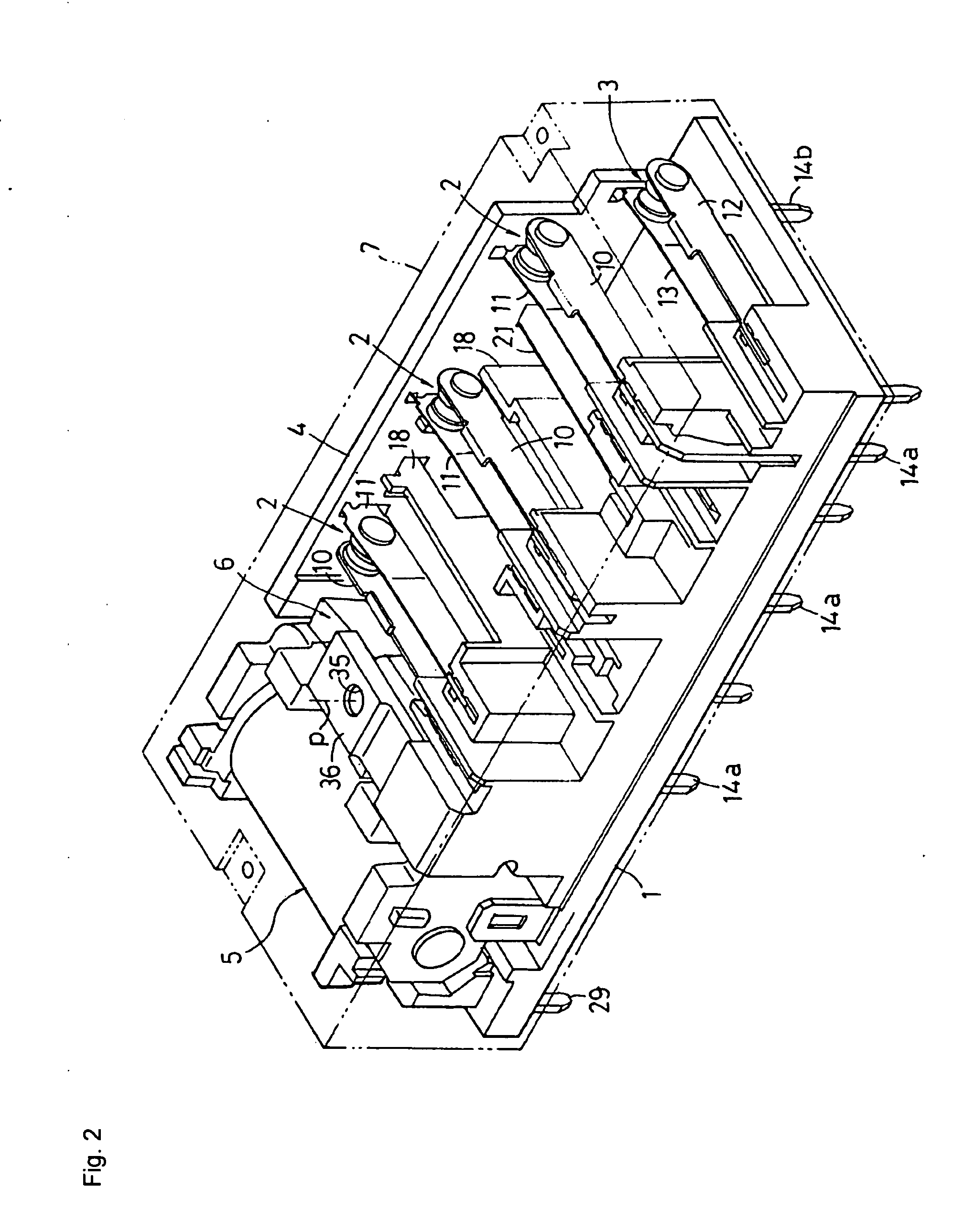
[0037]FIG. 1 shows a transverse plan view of an electromagnetic relay according to the invention, FIG. 2 shows a perspective view of an internal structure of the electromagnetic relay, and FIG. 3 shows a perspective view in which a base and a contact mechanism are taken apart.

[0038] The electromagnetic relay mainly includes a base 1, multipolar contact mechanisms 2 and 3, a card 4, an electromagnetic block 5, a card driving movable block 6, and an enclosure 7. The base 1 is molded by a resin material. The base 1 is long in a lateral direction and narrow in a cross direction. The contact mechanisms 2 and 3 are assembled to the base 1 in upper and lower stages. The card 4 is a contact switching moving body which is guided and supported on a rear side of the base 1 (upper side in FIG. 1) while being linearly reciprocally movable in the lateral direction. The electromagnet...


PUM


Abstract

An electromagnetic block and a movable block are attached onto a base in an inclination attitude. Contact mechanisms press-fitted from above the base are laterally arranged in the inclination attitude, and the contact mechanisms are arranged in parallel in upper and lower stages. Idle end portions of movable contact pieces in the contact mechanisms are latched in a card which is linearly moved in a lateral direction. Terminals are projected downward from a bottom surface of the base, one of the terminals is connected to the fixed contact pieces of the contact mechanism, and the other terminal is connected to the movable contact pieces of the contact mechanism. The upper contact mechanism and the lower contact mechanism are alternately arranged in the lateral direction.

Description

[0001] This application claims priority from Japanese patent application P2005-166704, filed on Jun. 7, 2005. The entire content of the aforementioned application is incorporated herein by reference. BACKGROUND OF THE INVENTION [0002] 1. Field of the Invention [0003] The present invention relates to a multipolar electromagnetic relay including plural contact mechanisms. [0004] 2. Description of the Related Art [0005] For example, in Japanese Patent Application Laid-Open No. 2000-285782 discloses a multipolar electromagnetic relay, in which an electromagnetic block and a movable block are assembled in a longitudinal attitude on a base formed by resin molding, plural contact mechanisms are laterally provided in parallel in two rows while sandwiching a partition, and terminals extended from the respective contact mechanisms are projected from a bottom surface of the base. [0006] In the electromagnetic relay disclosed in Japanese Patent Application Laid-Open No. 2000-285782, although a ...

Claims


Application Information

Patent Timeline
Patent Type & Authority Applications(United States)
IPC IPC(8): H01H51/22
CPCH01H50/023H01H50/026H01H50/043H01H2050/044H01H50/24H01H50/642H01H2050/028H01H50/14
Inventor TAKAYAMA, YOHEIARAI, HIROKITAKEBAYASHI, YASUHIRO
Owner ORMON CORP
Why Eureka
Try Eureka