Stand alone surveillance system

a technology of surveillance system and stand-alone monitoring, which is applied in the direction of burglar alarm, alarm, instruments, etc., can solve the problems of difficult to provide electrical power to security systems, and difficult to provide power to security systems at remote construction locations

Inactive Publication Date: 2006-12-14
NAZARI SOHEIL
View PDF24 Cites 51 Cited by
  • Summary
  • Abstract
  • Description
  • Claims
  • Application Information

AI Technical Summary

Benefits of technology

[0010] According to yet another aspect, a surveillance method is provided. The method comprises self generating power from a self-generating power source which may be a wind generator, a hydroelectric generator, one or more batteries, a hydrogen fuel cell or at least one solar panel. The method further includes directing the power to a DVR and at least one video camera disposed at a unit. The method further includes each video camera obtaining digital signals of video images and providing the digital signals to the DVR. The DVR records the images and the video signals corresponding to each camera are wirelessly transmitted from the DVR to a receiver. The method further provides for the receiver providing a video image corresponding to each video signal to the internet.

Problems solved by technology

It is difficult to provide electrical power in many cases where the security systems are used at remote locations.
For example, it is difficult to provide power to security systems desired at remote construction locations where electrical power has not yet been provided.
It is similarly difficult to provide electrical power to security systems that may be desired in undeveloped regions such as along national borders.
Moreover, when the security system is used to monitor multiple locations that may be spread out over acres or miles, it is even more problematic to provide power to the various locations

Method used


Image

  • Stand alone surveillance system
  • Stand alone surveillance system
  • Stand alone surveillance system

Examples


Embodiment Construction

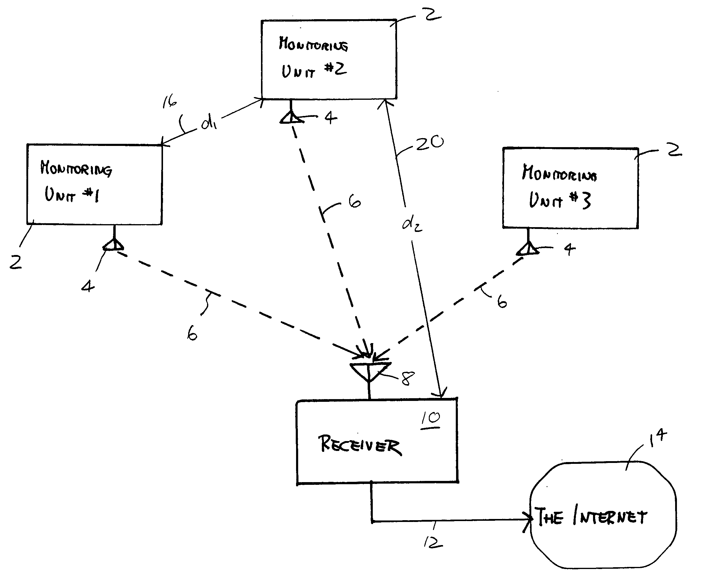
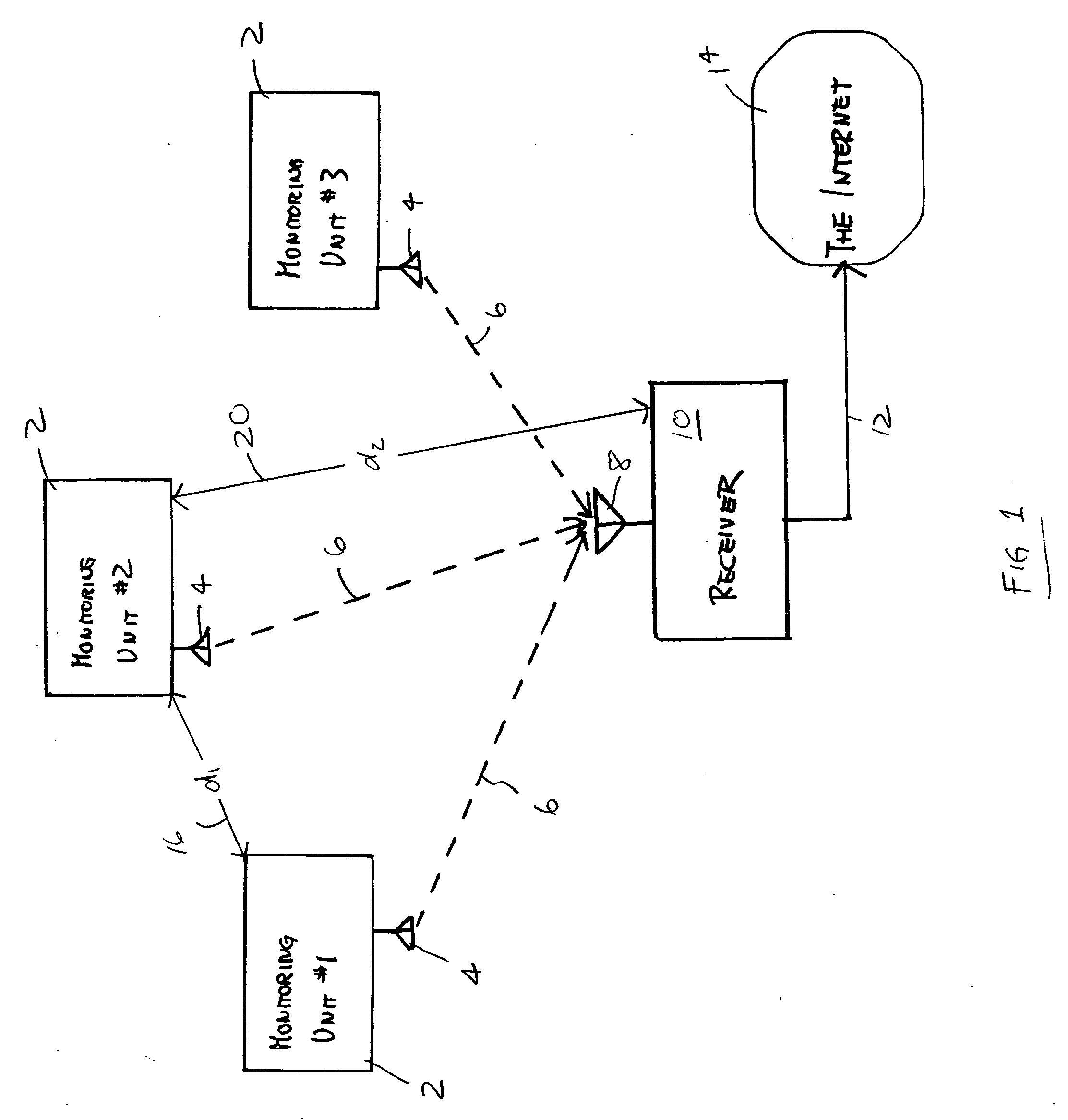
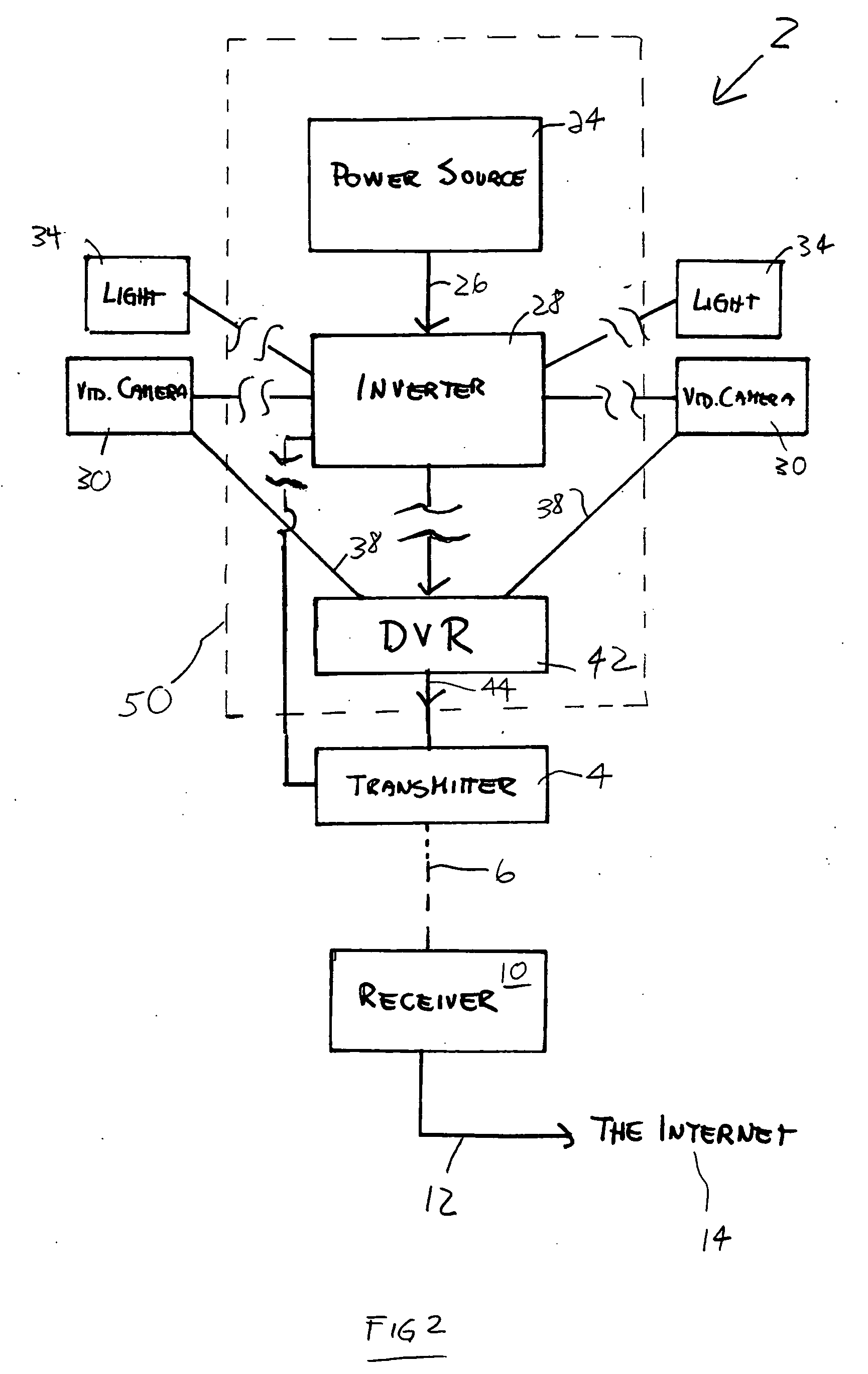
[0020] The invention provides a surveillance system that includes self-powering monitoring units that may be placed in remote locations far from electric power and far from internet access. The self-powering units may be powered by a plurality of batteries, a fuel cell such as a hydrogen fuel cell, a hydroelectric generator, a wind generator, or one or more solar cells. The power source provides power, through an inverter, to one or more cameras, one or more lights, one or more infrared illuminators, a transmitter / receiver and various other electrical peripherals at the monitoring unit. Among the electrical peripherals are an electrical temperature control system of the monitoring unit, a system for electronic card access into the monitoring unit, additional power provided to an external power output receptacle and a digital readout corresponding to the external power output receptacle and indicating the amount of additional power that may be used without compromising the integrity ...


PUM


Abstract

A surveillance system provides a plurality of monitoring units placed in remote locations without access to electrical power. Each monitoring unit includes a self-powering source including at least one of batteries, solar cells, a hydroelectric generator, a wind generator and a hydrogen fuel cell. The power source provides power to surveillance components such as cameras, lights, infrared illuminators, DVRs, and transmitters. The power source also provides power to other components in the housing of the monitoring units such as temperature control, keycard access, and excess power made available at an outlet at the housing. Each monitoring unit wirelessly transmits video signals from each of the cameras to a hub or receiver that directs the images to the internet. An internet user with the proper access code can access the video surveillance and remotely control the cameras and other components of the monitoring units.

Description

RELATED APPLICATION[0001] This application claims priority of U.S. Provisional Application Ser. No. 60 / 683,579 filed May 23, 2005, the contents of which are herein incorporated by reference as if set forth in their entirety.FIELD OF THE INVENTION [0002] The present invention relates to surveillance systems that may be placed at remote sites and which record activities at the remote sites. BACKGROUND [0003] Surveillance systems, particularly video monitoring security systems, are popularly utilized in both residential and commercial areas, at shopping malls, construction sites, and border areas and virtually at any location at which it would be beneficial to monitor activities. Such systems provide security by deterring unlawful or otherwise improper activities, minimizing losses, maximizing worker productivity, identifying the causes of accidents and crimes and so forth. There are various surveillance systems currently available that capture images from the location of the surveilla...

Claims


Application Information

Patent Timeline
Patent Type & Authority Applications(United States)
IPC IPC(8): G08B13/00
CPCG08B13/19632G08B13/19634G08B25/009G08B13/19693G08B13/19643
Inventor NAZARI, SOHEIL
Owner NAZARI SOHEIL
Why Eureka
Try Eureka