

Antenna
Active Publication Date: 2006-12-14
COMMSCOPE TECH LLC
View PDF16 Cites 25 Cited by
- Summary
- Abstract
- Description
- Claims
- Application Information
AI Technical Summary
Problems solved by technology
This leads to an increase in part quantity, cost, assembly time, weight and complexity.
This system would result in a substantial decrease in half power bandwidth and is therefore not suitable for use in a panel antenna for wireless communications systems.
Method used
View moreImage
Smart ImageViewing Examples

Examples
first embodiment
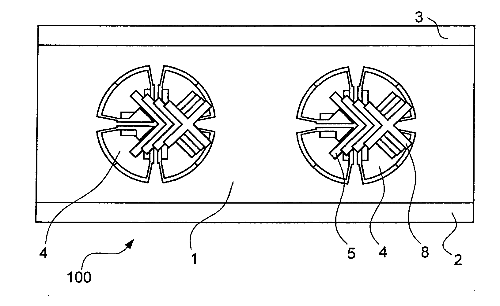
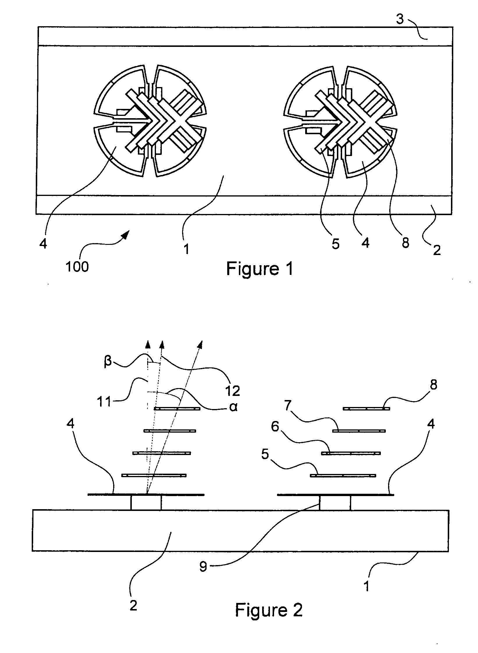
[0028]FIG. 1 is a top view of a panel antenna ;
[0029]FIG. 2 is a side view of the antenna of FIG. 1;
second embodiment
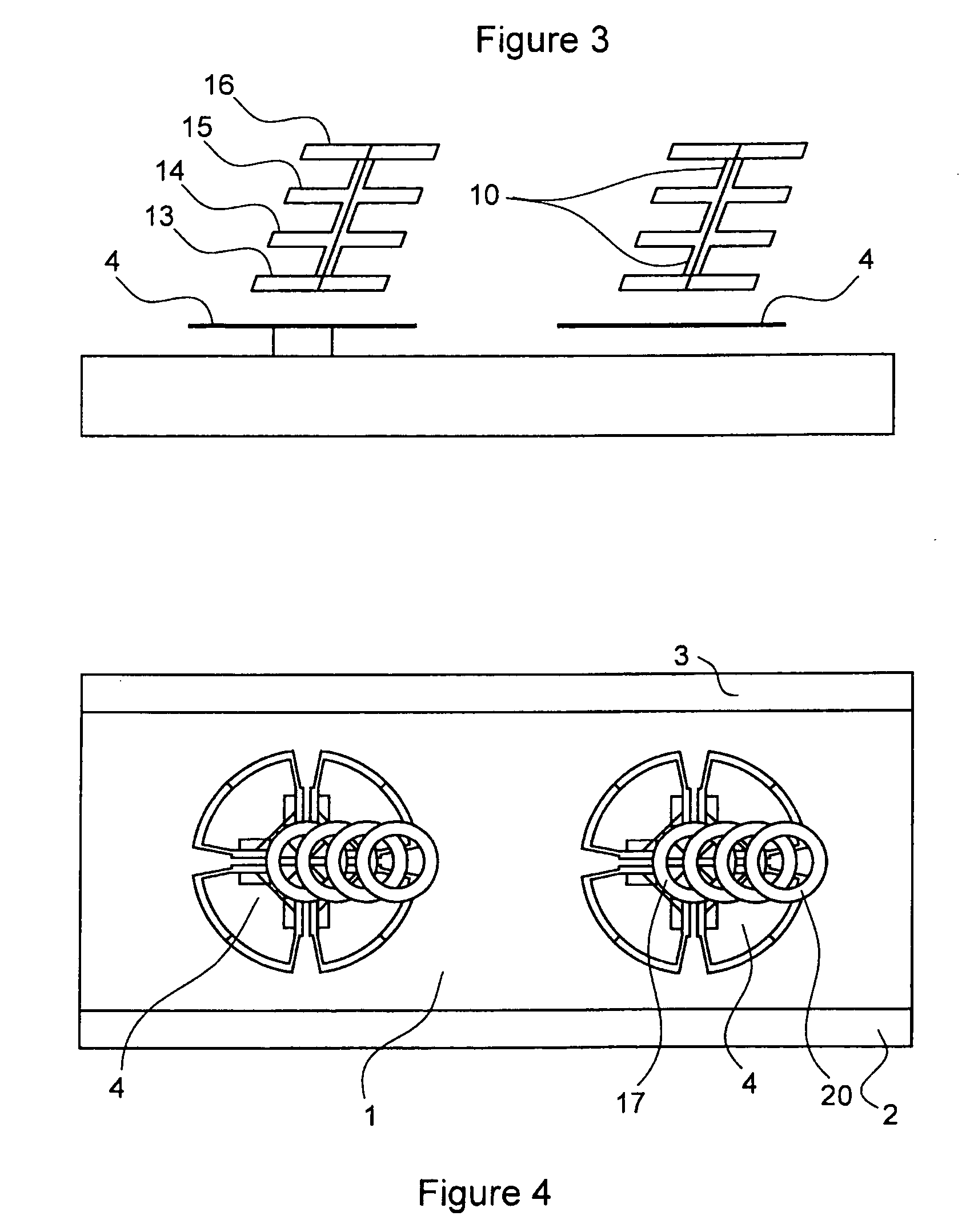
[0030]FIG. 3 is a side view of a panel antenna ;
third embodiment
[0031]FIG. 4 is a top view of a panel antenna ;
[0032]FIG. 5 is a side view of the antenna of FIG. 4;
Login to View More PUM
 Abstract
A panel antenna is provided having one or more radiating elements and a series of directors associated with each radiating element. Each series of directors is angled with respect to a direction of maximum radiation of the associated radiating element, in order to tilt the panel antenna beam. The directors may be dimensioned and / or arranged such that they couple weakly to radiation of a wavelength emitted by the associated radiating element. The directors may be dimensioned and / or arranged such that they are non-resonant at the wavelength emitted by the associated radiating element. The directors may be smaller than the length of an associated dipole radiating element.
Description
FIELD OF THE INVENTION [0001] The invention relates to antennas. In particular the invention relates to antennas for use in wireless communication networks, such as cellular telecommunications systems. BACKGROUND OF THE INVENTION [0002] Wireless communications networks may be divided into cells, with each base station antenna in the network servicing a cell. Base station antennas generally tilt their beams downwards, towards the mobile handsets carried by users and to minimise energy radiated above the horizon. However, the simplest antenna geometry places radiating elements in a plane parallel to a vertical reflecting ground plane. This causes energy to be radiated equally above and below the horizon. [0003] Various methods of achieving downtilt of the antenna radiation pattern have been proposed. In an antenna array, downtilt may be adjusted by arrangement of phase relationships between radiating elements. Alternatively, the radiation pattern of each radiating element may be tilte...
Claims
Login to View More Application Information
Patent Timeline
 IPC IPC(8): H01Q19/10H01Q21/26
CPCH01Q1/246H01Q3/30H01Q21/26H01Q19/30H01Q9/26
InventorZIMMERMAN, MARTIN L.
OwnerCOMMSCOPE TECH LLC