Washing apparatus, washing stystem, and washing method

a technology of washing apparatus and washing stystem, which is applied in the direction of cleaning process and apparatus, cleaning apparatus, chemistry apparatus and process, etc., can solve the problems of difficulty in cleaning the groove, and more conspicuous level, so as to facilitate the removal of waterdrops and reduce the cost

Inactive Publication Date: 2006-12-14
SHIN-ETSU HANDOTAI CO LTD
View PDF6 Cites 33 Cited by
  • Summary
  • Abstract
  • Description
  • Claims
  • Application Information

AI Technical Summary

Benefits of technology

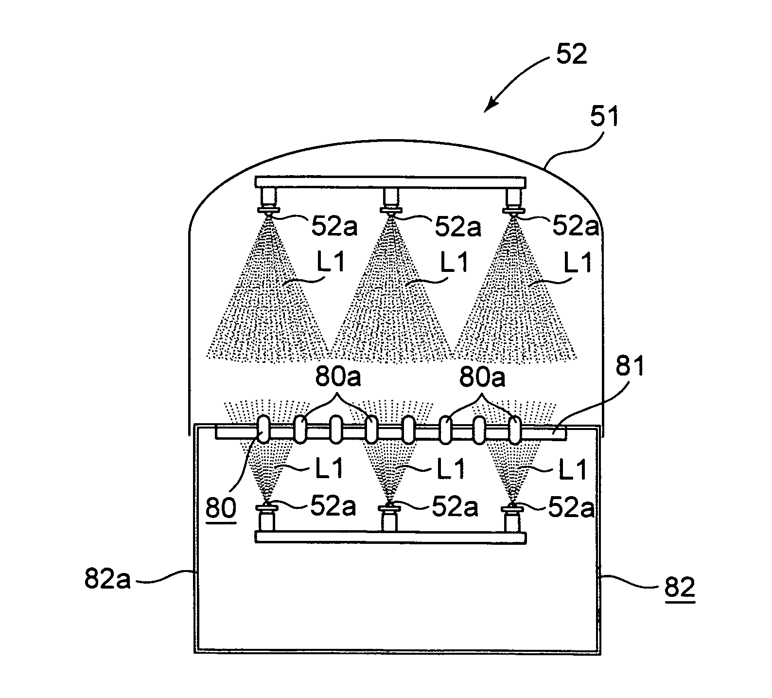
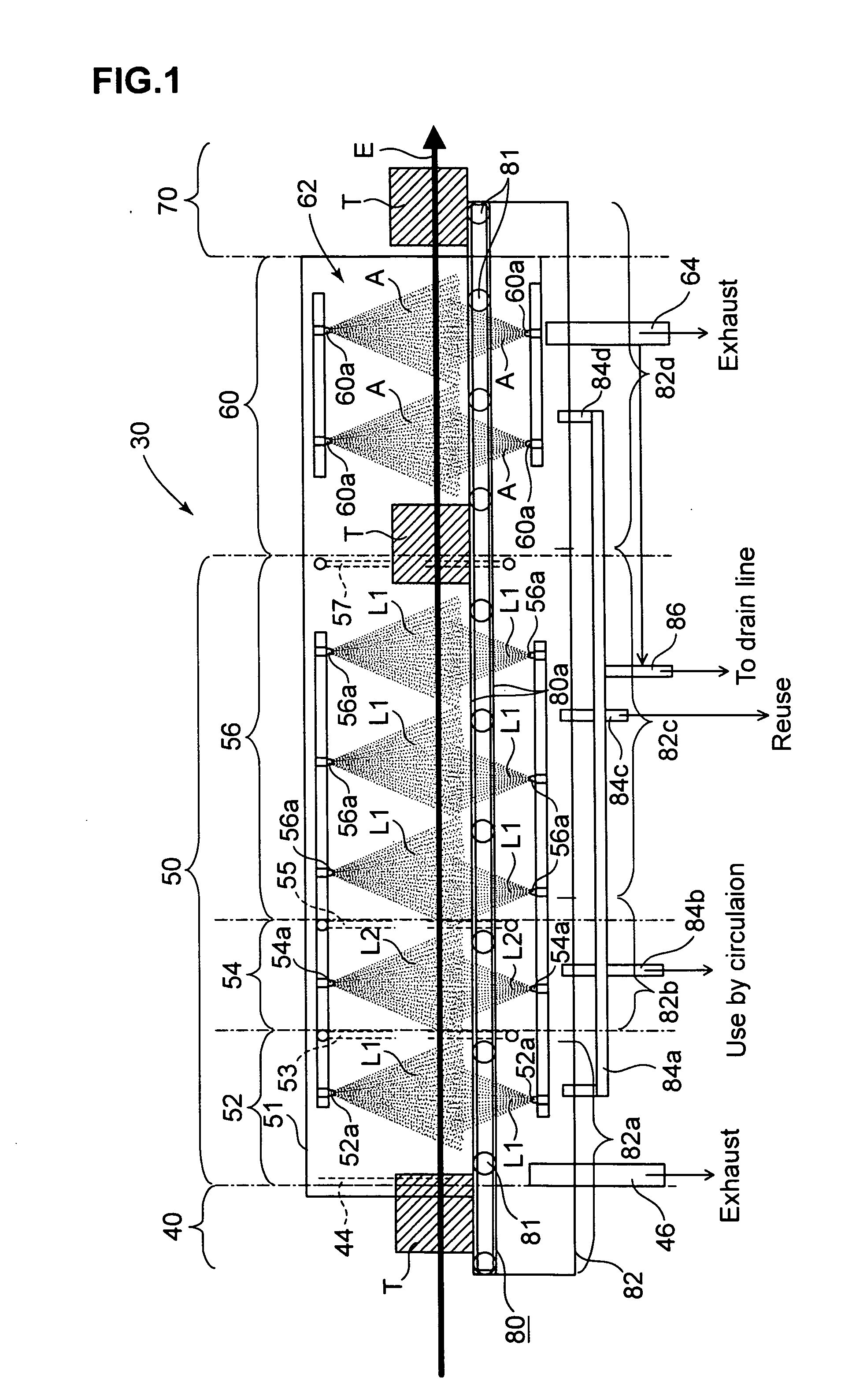
[0025] In the construction of the plural cleaning sections, water curtains are provided after the cleaning section, between the precleaning section and the chemical solution cleaning section, and between a chemical solution cleaning section and the rinse section, respectively. With such a construction adopted, the cleaning sections are clearly defined, and hence it is prevented that droplets are mixed, especially droplets of the chemical solution cleaning section are mixed into the precleaning section or into the rinse section. Besides, while very small waterdrops are attached to the member to be cleaned, the member passes through the water curtain to thereby grow the very small waterdrops to a large size waterdrop and to facilitate the waterdrops to be removed.
[0026] Incidentally, for the cleaning liquid (pure water) to be supplied in the precleaning section, the cleaning liquid (pure water) used in the rinse section may be preferably used according to a circulation system. With such recycling applied, pure water or the like is effectively used, resulting in decrease in cost.

Problems solved by technology

A cleaning apparatus and a cleaning method conventionally adopted, which are described above, have had various problems in aspects of an operation efficiency, a quality level and an apparatus cost.
For example, in brush cleaning, tips of bristles of a brush are difficult to intrude into grooves into which wafers are inserted in a wafer accommodating container or the like, which makes it hard to clean the grooves and moreover, since depths of grooves are deepened in company with increase in diameter of a wafer, such a problem has revealed in a more conspicuous level.
Therefore, cleaning has been more and more difficult in company with increase in wafer diameter.
Besides, automation has also been difficult in brush cleaning, because the wafers have complex shapes, various sizes and differences in their shapes.

Method used


Image

  • Washing apparatus, washing stystem, and washing method
  • Washing apparatus, washing stystem, and washing method
  • Washing apparatus, washing stystem, and washing method

Examples


empirical example 1

[0096] Experiments here were conducted in order to confirm a removing capability of particles on a conventional dipping method, a conventional shower method and the high pressure spraying method of the present invention. Comparison on particle removing capability in the same condition is difficult between particle removing methods that are different in principle of removing particles from one another; therefore, in the experiments, especially in order to confirm the removing capability for very small size particles, overall cleaning conditions were determined in three methods including the conventional dipping method, the conventional shower method and the high pressure spraying method of the present invention so that particles with a size of 0.5 μm or more were at the same level (5 particles or less), and comparison was performed on the removing capability (the cleaning capability) of particles with a size of 0.5 μm or less. Cleaning by the three methods using a cleaning liquid con...

example 1

[0103] An example was shown in which the cleaning system shown in FIGS. 1 to 16 was employed and there was cleaned a polycarbonate wafer accommodating container, as shown in FIGS. 17 to 19, capable of accommodating 25 silicon wafers each with a diameter of 200 mm used in the semiconductor field. The accommodating container is constituted of a cover, a substrate presser (a retainer), a substrate accommodating cassette (an inner cassette), a packing (a gasket), and a container body (a lower box), which are necessarily cleaned. Incidentally, in the cleaning system of the present invention, the retainer and the gasket can be individually cleaned, while in this example, plural pieces are collectively put into a basket, transported and cleaned.

[0104] In this example, the cover and the container body that constitute the accommodating container and are in the concave shape are set on the loader section of the cleaning system each in a state of facing an opening thereof downward. The above ...


PUM


Abstract

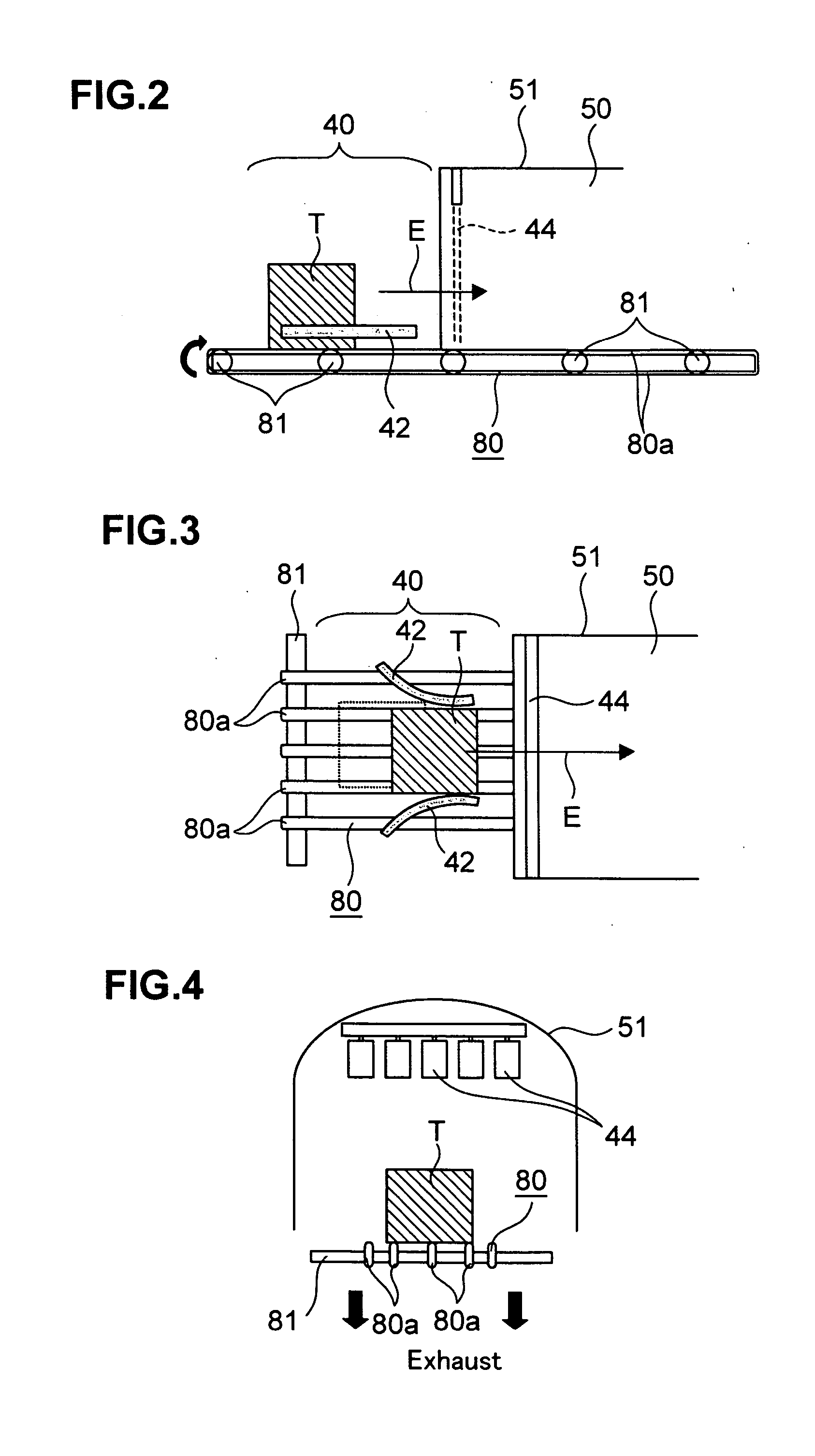
The present invention provides a cleaning apparatus, a cleaning system and a cleaning method for a member used in the semiconductor field, excellent in cleaning capability and good in operation efficiency. The present invention is directed to a cleaning apparatus for cleaning the member used in the semiconductor field, which comprises: one nozzle or plural nozzles; and a jet mechanism for jetting a mist-like cleaning liquid (L1) with a high pressure from the one nozzle or the plural nozzles (52a) to the member (T) to be cleaned. The present invention is also directed to a cleaning system (30) for cleaning members used in the semiconductor field, which comprises: a loader section (40) for setting a member to be cleaned; an unloader section (70) for collecting the members; and a transport stage (80) for continuously transporting the member from the loader section to the unloader section, wherein a cleaning section (50) for cleaning the member with a mist-like cleaning liquid is provided on the transport stage, and the member is transported by the transport stage and is also cleaned in the cleaning section.

Description

TECHNICAL FIELD [0001] The present invention relates to a cleaning technique for a member (a member to be cleaned) used in the semiconductor field, and in particular, to a cleaning apparatus for a wafer accommodating container used in a field in which a cleanliness level is severely demanded by a user such as, especially, a wafer maker or a semiconductor maker (or a device maker) and for a wafer carrier employed between processes, to a cleaning system excellent in cleaning effect and good in operability and to a cleaning method for cleaning the member to be cleaned. BACKGROUND ART [0002] In a progress in recent miniaturization of devices accompanied with a higher level of integration in semiconductor circuits such as semiconductor devices, a quality requirement for a wafer serving as a substrate therefor has been progressively enhanced. More of attention has been directed to contamination due to dust on the micron order or the submicron order in particle size as a problem. Such dust...

Claims


Application Information

Patent Timeline
Patent Type & Authority Applications(United States)
IPC IPC(8): H01L21/00H01L21/302H01L21/304B08B3/02
CPCH01L21/67051B08B3/022
Inventor OSE, HIROKIYOKOTA, SHUJI
Owner SHIN-ETSU HANDOTAI CO LTD
Why Eureka
Try Eureka