
DMB data receiving apparatus and method for improving DMB data receiving speed

a technology for receiving apparatus and data, applied in the field of digital multimedia broadcasting, can solve the problems of high probability of error occurrence, inability to check whether or not broadcasted dmb data have been received without, and inability to guarantee that msc data, which have not been received or received with errors, can be received without errors, etc., to achieve the effect of improving the data receiving speed

Active Publication Date: 2006-12-14
SAMSUNG ELECTRONICS CO LTD
View PDF5 Cites 28 Cited by
  • Summary
  • Abstract
  • Description
  • Claims
  • Application Information

AI Technical Summary

Benefits of technology

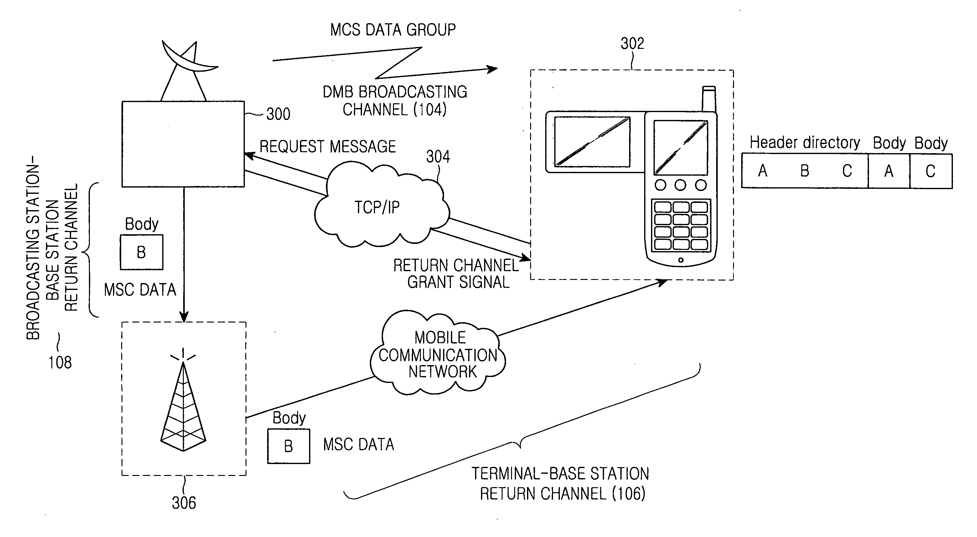
[0019] Accordingly, the present invention has been made to solve the above-mentioned problems occurring in the prior art and provides additional advantages, by providing a DMB data receiving apparatus and its related method capable of improving a data receiving speed when a DMB reception terminal receives DMB data broadcasted through a DMB broadcast channel.

Problems solved by technology

That is, when providing a data service using a broadcasting signal based on the MOT protocol, a DMB (Digital Multimedia Broadcasting) broadcasting station only broadcasts broadcast data to DMB reception terminals, but has no way of checking whether or not the broadcasted DMB data have been received without any error by the DMB reception terminals.
However, when the user receives MOT data while he / she is moving, the probability of error occurrence becomes high.
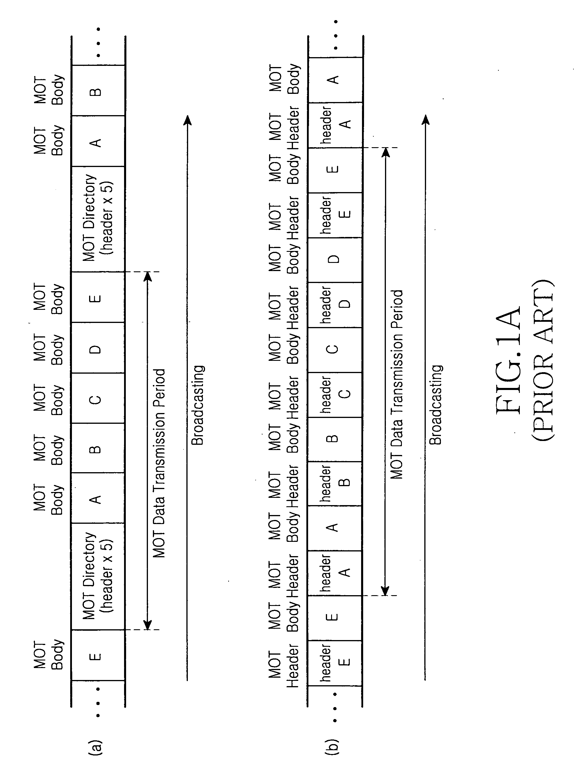
Furthermore, it is impossible to guarantee that MSC data, which have not been received or received with error, can be received without an error during the next MOT data transmission period.

Method used


Image

  • DMB data receiving apparatus and method for improving DMB data receiving speed
  • DMB data receiving apparatus and method for improving DMB data receiving speed
  • DMB data receiving apparatus and method for improving DMB data receiving speed

Examples


Embodiment Construction

[0030] Hereinafter, an embodiment of the present invention will be described with reference to the accompanying drawings. It is to be noted that the same elements are indicated with the same reference numerals throughout the drawings. For the purposes of clarity and simplicity, a detailed description of known functions and configurations incorporated herein will be omitted as it may obscure the subject matter of the present invention.

[0031] The current terrestrial DMB (Digital Multimedia Broadcasting) reception terminal has the functions of a mobile terminal (that is, a communication function, a short message service (SMS) reception function, and a multimedia message service (MMS) reception function) as well as a DMB reception function. To this end, the current DMB reception terminal uses an additional transmission route, as well as a transmission route for DMB broadcasting, to establish a two-way communication. One exemplary mobile terminals having such a function is a DMB phone, ...


PUM


Abstract

Disclosed is a DMB data receiving apparatus and method for improving a DMB data receiving speed. According to the DMB data receiving apparatus and method, if there are predetermined MSC data, which have not been received or received with an error when receiving MSC data by a DMB reception terminal, the DMB reception terminal can receive the predetermined MSC data through a return channel established between the DMB reception terminal and a broadcasting station. In detail, if there are predetermined MSC data, which have not been received or received with an error, the DMB reception terminal request the broadcasting station to transmit the predetermined MSC data and to allow establishment of a return channel, and then receives the predetermined MSC data through a return channel established based on the request. Therefore, when some MOT content data have not been received or received with an error, the DMB reception terminal can immediately receive the corresponding MOT content data without waiting until the next MOT data transmission period begins, thereby greatly improving the DMB data receiving speed.

Description

CLAIM OF PRIORITY [0001] This application claims the benefit under 35 U.S.C. 119(a) of an application entitled “DMB Data Receiving Apparatus And Method For Improving DMB Data Receiving Speed,” filed in the Korean Intellectual Property Office on Jun. 14, 2005 and assigned Serial No. 2005-50993, the entire contents of which are incorporated herein by reference. BACKGROUND OF THE INVENTION [0002] 1. Field of the Invention [0003] The present invention relates to digital multimedia broadcasting (DMB), and more particularly to an apparatus and method for receiving data broadcasted through a DMB data broadcast channel. [0004] 2. Description of the Related Art [0005] A terrestrial DMB technology enables reception broadcast signals while a user roaming. The terrestrial DMB is based on the European-type digital audio broadcasting (DAB) standard, which provides a data service, as well as video and audio services, through a DMB data broadcast channel. [0006] Broadcast protocols for broadcasting...

Claims


Application Information

Patent Timeline
IPC IPC(8): H04Q7/22H04B1/16H04H1/00H04H20/16H04H20/24H04H20/28H04H20/57H04H60/12H04H60/82H04H60/85H04H60/91H04N5/44H04N7/173
CPCH04H20/16H04H20/24H04H20/57H04H2201/37H04H60/82H04H60/91H04H2201/30H04H60/12H04N7/00H04N7/015H04W4/12
Inventor JUNG, JI-WUCKKIM, YOUNG-JIPKIM, HYUN-CHUL
Owner SAMSUNG ELECTRONICS CO LTD
Learn More