Eureka AIR delivers breakthrough ideas for toughest innovation challenges, trusted by R&D personnel around the world.

Vertebral facet stabilizer

a facet stabilizer and vertebral technology, applied in the field of facet stabilizers, can solve the problems of slow fusion rate, arthrodesis poses problems of its own, poor treatment effect, etc., and achieves the effect of enhancing the flexibility of one or more embodiments

Inactive Publication Date: 2006-12-14
ALTUS PARTNERS
View PDF33 Cites 180 Cited by
  • Summary
  • Abstract
  • Description
  • Claims
  • Application Information

AI Technical Summary

Benefits of technology

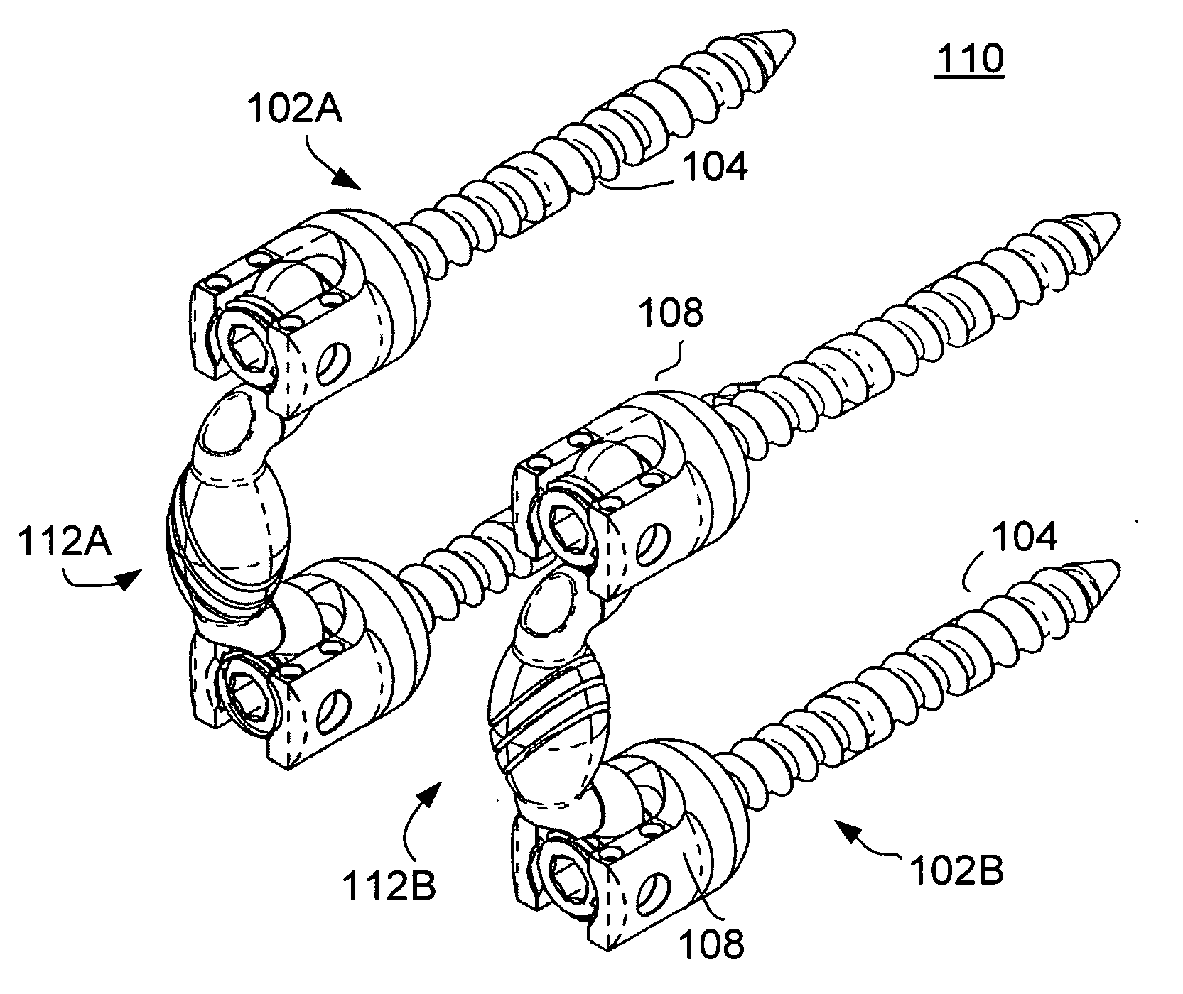
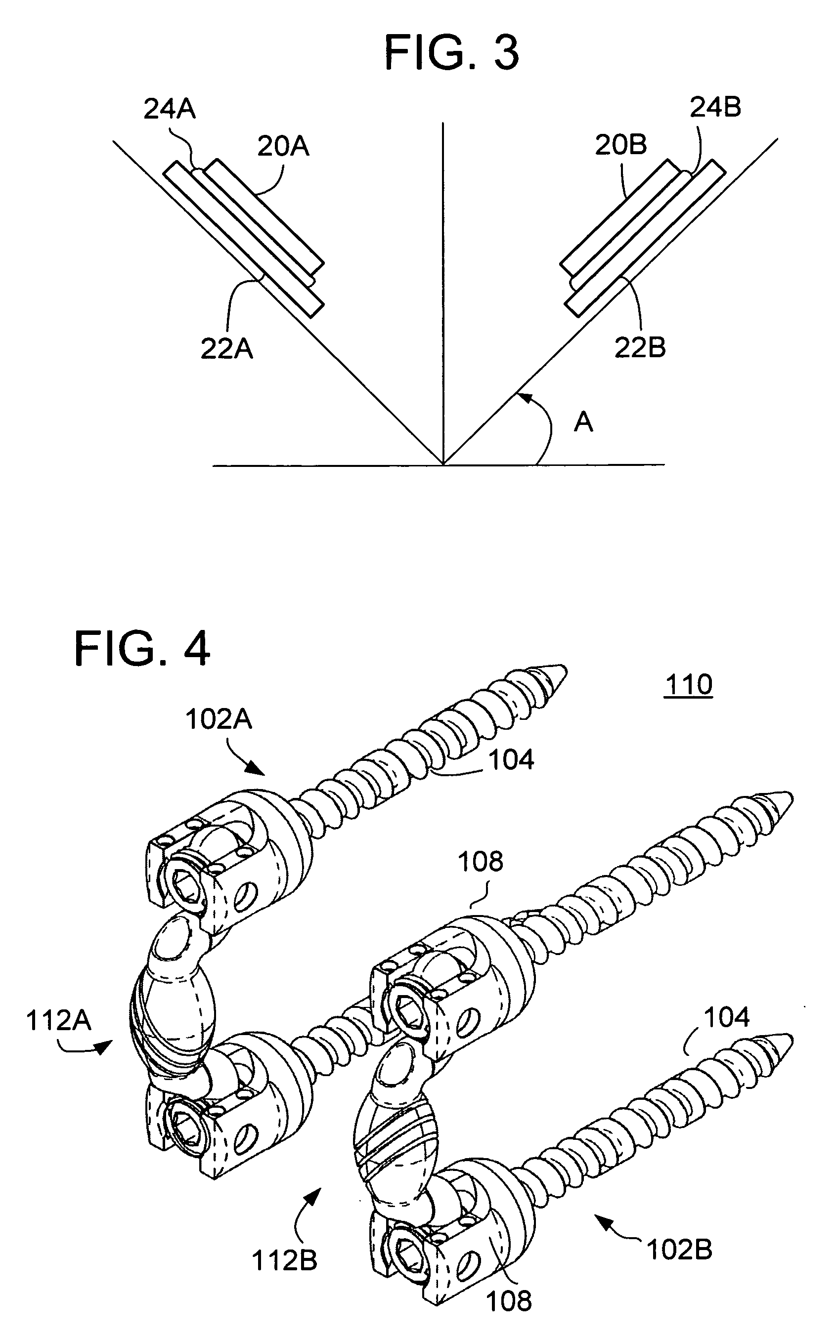
[0014] The skewed helical cut or skewed through cut provides proper anatomical and physiological constraints for vertebral range of motion. The spring element may be offset from the pedicle screws. The offset provides proper orientation of the slots or cuts for restoration of proper kinematics. For example, the orientation of the skewed cut plane should be similar to the plane generated by facets on the instrumented level (facet plane). The offset also provides an increase in the moment arm and minimizes the reaction on the device due to rotation of the spinal column. Embodiments without the offset, but with the skewed helical-cut or skewed through-cut can also be used; however, they will not maximize posterior offset and will require additional care for proper orientation of the cut with respect to the facet plane.
[0016] The flexibility of one or more embodiments may be enhanced by including an elastic insert either inside the cylindrical section of the rod or between through-cut surfaces.

Problems solved by technology

Furthermore, although patients with one or two levels of spinal stenosis tend to do reasonably well with just a one to two level wide decompressive laminectomy, patients whose spinal stenosis is associated with degenerative spondylolisthesis have not seen good results.
Although patients who undergo concomitant arthrodesis do demonstrate a significantly better outcome with less chance of further vertebral slippage after laminectomy, arthrodesis poses problems of its own.
Aside from the occurrence of further spondylolisthesis in some patients, additional effects include non-unions, slow rate of fusion even with autografts, and significant morbidity at the graft donor site.
Furthermore, even if the fusion is successful, joint motion is totally eliminated at the fusion site, creating additional stress on healthy segments of the spine which can lead to disc degeneration, herniation, instability spondylolysis, and facet joint arthritis in the healthy segments.
Although different designs achieve different levels of success with patients, disc replacement mainly helps patients with injured or diseased discs; disc replacement does not address spine pathologies such as spondylolisthesis and spinal stenosis caused by facet joint degeneration or disease.

Method used


Image

  • Vertebral facet stabilizer
  • Vertebral facet stabilizer
  • Vertebral facet stabilizer

Examples


Embodiment Construction

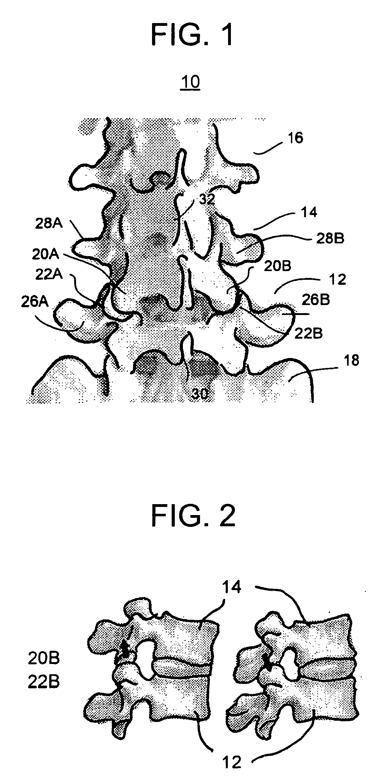
[0039] Reference is now made to FIG. 1, which is a posterior view of a portion of a spinal column 10, specifically in the lumbar region. Although the lumbar region of the spine 10 is being discussed herein for illustration, it is understood that the embodiments of the invention are not limited to use in the lumbar region, although that region is preferred. The spinal column 10 includes a plurality of levels, where each level includes a vertebral body 12, 14, 16, etc. The sacrum 18 is partially shown below the various levels of the spinal column 10.

[0040] The vertebral body 14 includes superior facet 20A on one side of the spinous process 32 and another superior facet 20B on the other side of the spinous process 32. The vertebral body 14 also includes a pedicle 28A on one side and pedicle 28B on the other side of the spinous process. The next lower vertebral body 12 includes an inferior facet 22A on one side of the spinous process 32 forming a joint with the superior facet 20A, and ...


PUM


Abstract

An vertebral stabilizer includes a spring element defining a longitudinal axis and having first and second ends, each operable to couple to respective first and second bone anchors of a patient, wherein the spring element includes a slanted coil element operable to produce a reaction force in a direction transverse to the longitudinal axis.

Description

CROSS REFERENCE TO RELATED APPLICATIONS [0001] This application claims the benefit of U.S. Provisional Patent Application No. 60 / 688,421, filed Jun. 8, 2005, the entire disclosure of which is hereby incorporated by reference.BACKGROUND [0002] The present invention generally relates to devices and surgical methods for the treatment of various types of spinal pathologies. More specifically, the present invention is directed to facet stabilization, such as in connection with facet replacement or facet resurfacing. [0003] Back pain is a common human ailment. In fact, approximately 50% of persons who are over 60 years old suffer from lower back pain. Although many incidences of back pain are due to sprains or muscle strains which tend to be self-limited, some back pain is the result of more chronic fibromuscular, osteoarthritic, or ankylosing spondolytic processes of the lumbosacral area. Particularly in the population of over 50 year olds, and most commonly in women, degenerative spine ...

Claims


Application Information

Patent Timeline
IPC IPC(8): A61B17/70A61F2/44
CPCA61B17/7004A61B17/7011A61B17/7025A61B17/705A61B17/7032A61B17/7049A61B17/7028
Inventor ALBERT, TODD JAMESZUBOK, RAFAILKVITNITSKY, MIKHAIL
Owner ALTUS PARTNERS
Why Eureka
Eureka Blog
Learn More